
843-297-8348 [email protected]
- E-Panel Builder
- Fully Custom
- Printed Contura II
- Etched Contura V
- Push Buttons
- Toggle Switches
- Circuit Protection
- Accessories (all)
- Marine Wire
- Battery Switches
- Mounting Panels
- Plugs & Chargers
- Terminal Blocks & Bus Bars
- Terminals & Lugs
- Deutsch Compatible Connectors
- Meters & Gauges
- Merch & Gift Cards
- 1. Panel Buyer’s Guide
- 2. Switch Panel Options
- 3. Panel Material
- 4. Switch Label Options
- 5. Printed vs. Etched Switch Covers
- 7. Wiring Diagrams
- 8. Boat Wiring Basics
- 9. Before and After
- 10. LuxMatte
- Panel Projects
How To Wire (or re-wire) a boat
I know what you’re thinking. “ How is this lunatic going to cover such a complex topic as – how to wire a boat – in one post? ”
Well – you’re right – We won’t be able to cover every situation, or every possible setup on every boat. And if all this info is new to you, you’re probably best hiring a professional marine electrician to do it for you ( local install support directory ). But, we’ll try anyway to explain some of the general theory and best practices in hopes it will help.
In this guide we’ll stick with the 12Vdc power distributions systems, as opposed to engine or gauge wiring.
A few notes before we start:
- Positive wires are red (in our guide, your boat may have other colors)
- Negative wires are black (or may be yellow on your boat)
- Current is measured in Amps (A)
- Potential difference is measured in Volts (V)
- Current flows through the wires (like water through a pipe). Too much current can heat up the wiring to the point of starting a fire
- Voltage does not “flow” it is a measurement of potential to do work. Like water pressure in a pipe
I’m in a hurry…
1. The Electrical Source: a Battery
In a boat, electricity is stored in one or more batteries. The batteries are charged by your engine’s alternator or auxiliary battery charger. They can hold an enormous amount of energy, capable of pushing hundreds, or even a thousand amps (more than your entire house uses)… so care must be taken, and proper circuit protection should not be ignored .
Greatly generalizing the topic here, but you usually run into two types of batteries in the size of boat we deal with:
- Starting Battery – Has high current rush capacity
- Deep Cycle Battery – Capable of deep discharge without harm
The two setups we most often run into is:
- Single Engine – 1 starting, and 1 house battery
- Twin Engine – 2 starting, and 1 house battery
Every non-engine wire (EVERY ONE) should be circuit protected with a fuse or circuit breaker
Batteries have positive and negative. For current to flow (which does the work) a complete circuit must be made from positive back to the negative. Any break in the circuit anywhere will stop the load from operating (which you probably already know or you wouldn’t be reading this to try and fix your marine wiring issue).

A normal battery might be able to push 800A or more current
A normal battery might have 70-80AH (amp hours) of capacity. Meaning it can run a 1A load for 70 to 80 hours, or a 10A load for 7 to 8 hours before it is discharged.
So let’s get our boat wiring diagram started with our batteries!
Tip: (use the tabs to view and hide notes).

Testimonial:
“Thanks Rob… I know you’re super busy – and this ain’t the biggest project in your shop, I’m sure. But the level of service I’ve gotten so far is five-star. Much appreciated. Have an awesome holiday!”
-Rick K. Angels Camp, CA
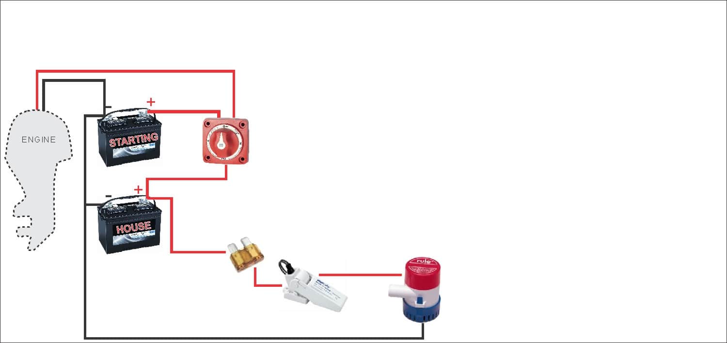
2. main battery switch.
In nearly all cases your boat wiring system should have a marine-grade main battery disconnect switch . This allows you to open the switch turning everything off at once. In this case, We’ve shown a 1-2-BOTH type battery switch.
Both battery positives are running through this switch, and you can use it to select which battery you want to output, similar to an A-B switch. But a 1-2-BOTH marine battery switch also allows you to parallel both batteries. Both settings might be used when you are running your engine and want to charge both batteries from the alternator, or if you need to parallel the batteries in an emergency to help start your engine if your start battery becomes too depleted.
Remember to turn your battery switch to the “house circuit” when your engine is not running, so you are only drawing down your deep cycle house battery meant for that purpose.
we’ve changed the diagram a bit now to show the start battery running through our new marine battery switch
A Double Pole ON/OFF/COMBINE battery switch ( like this one ) is a great choice for a single-engine, two battery boat wiring system. It allows your house and starts battery to remain isolated except for emergency conditions.

Used to shutoff everything and prevent trickle charges from draining your battery

3. Battery Switch Bypass Loads (Bilge Pump, etc)
It’s pretty standard in boat wiring to bypass the main battery switch for one thing: The boat’s bilge pump float switch. This way, even if your battery switch is off, if your boat starts filling with water the pump will still kick on. I’d rather have a dead battery than a swamped boat.
Notice the fuse shown – this needs to be circuit protected with an inline fuse like this one . I’m also showing the negative return wiring for the bilge pump in this step.
A stereo memory line might be another “bypassed” load
We have an in depth article here on how to wire a bilge pump … check that out as well for more details.

You’ll probably want to bypass your battery switch for this important load
“I have been thrilled with my new panel with a 3 foot harness. It looks great and using your tutorials I have been able to rewire my 10 year old center console. The support I received from New Wire Marine went above and beyond. Thank You!”
-Robert B. Bethesda, MD.

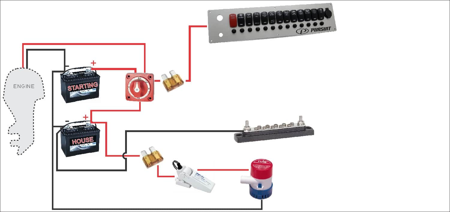
4. Get the Source to the Boat’s Helm
The next step is to get the power from the house battery up to the switch panel where we can use it to do some good. Two conductors – a positive from the battery switch (with a fuse) and a negative from the ganged together battery negatives should be ran to where the central switch panel is. You should use marine grade primary wire for this.
This is sometimes a long wiring run on a boat. Plus these two conductors will carry the current of all your electrical loads combined, so they are typically fairly beefy cables. Even a small boat (3-5 loads) we’d recommend at least 12AWG wire for this. 10AWG for larger boats (5-10 loads) is normal. 8AWG is getting toward over-kill in most cases for boats under 30ft.
Remember these are all generalities, there are many valid reasons to make exceptions
Keep in mind that the longer your wiring run from the battery to switch panel is, the more voltage drop you’ll have ( more about voltage drop ). Prevent voltage drop by using larger cable.
The power cables will be run to your New Wire Marine custom marine switch panel and your tinned marine negative bus bar . Most of our switch panels include waterproof resettable circuit breakers with all the connections pre-made to make them work, that’s how it is shown here.
Note, if you do not order circuit breakers in your boat switch panel you’d need to insert a fuse block before the panel, then individual conductors from each fuse to each panel (we really recommend including circuit breakers in your panel if you have space, it will really make your life easier installing and maintaining your new custom switch panel).
The main house battery positive conductor will feed directly into the new switch panel. The main battery negative should go to a negative buss bar (like this one), where all your boat’s load negatives will eventually be attached.

Example of one of our Switch Panels with Built in Circuit Breakers

Example negative bus bar. Note, this is different than a terminal block – all the screws are “bused” together.
“Excellent company and personnel! They asked the right questions and provided great solutions!”
-Tre McC. Houston, TX
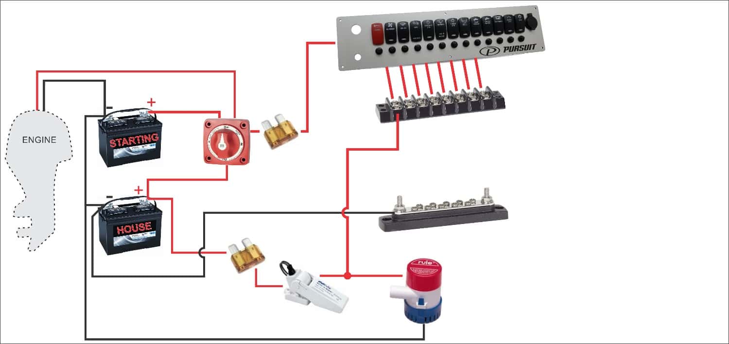
5. install terminal block as breakout point.
If you get your boat’s switch panel fully wired ( more on that here ), then you’ll have an easy to install wiring harness coming off pre-installed with heat shrink labels, and ring terminals. This is meant to land on a terminal block like this one .
Each switch output gets its own gang on the terminal block, and with the labels right there it makes a handy breakout point for troubleshooting or adding items down the road. These are the positives of course – the “switch legs” – and all that’s needed is to crimp a #8 ring terminal on the positive load wiring that runs out around your boat to the various loads.
We’re showing one output from the terminal block here for the manual bilge pump switch. It’s shown in parallel with the float switch, so either switch can turn the pump on ( read more about bilge pump wiring here ).

(click to enlarge)
This is how one of our fully wired switch panels would interface with a terminal block. With our heat shrink labels it’s easy to hook up your load wiring and troubleshoot.
“I have enjoyed working with the entire team, they have been super, just a great company to do business with.”
-Jim R. Vero Beach, FL

6. Run Load Wiring to the Terminal Block and Buss Bar
From here the rest of the wiring is straightforward. Just hookup your existing boat wiring infrastructure to the terminal block and buss bar. Positives to the terminal block, and negative to the bus bar.
Most are terminated with standard #8 ring terminals. The positives of course must be installed on the correct gang associated with the respective switch for that load. The negatives can go on any screw on the buss bar, they are just trying to get back to the negative post on the battery.

From here on our it’s just a + and – wire run to each load
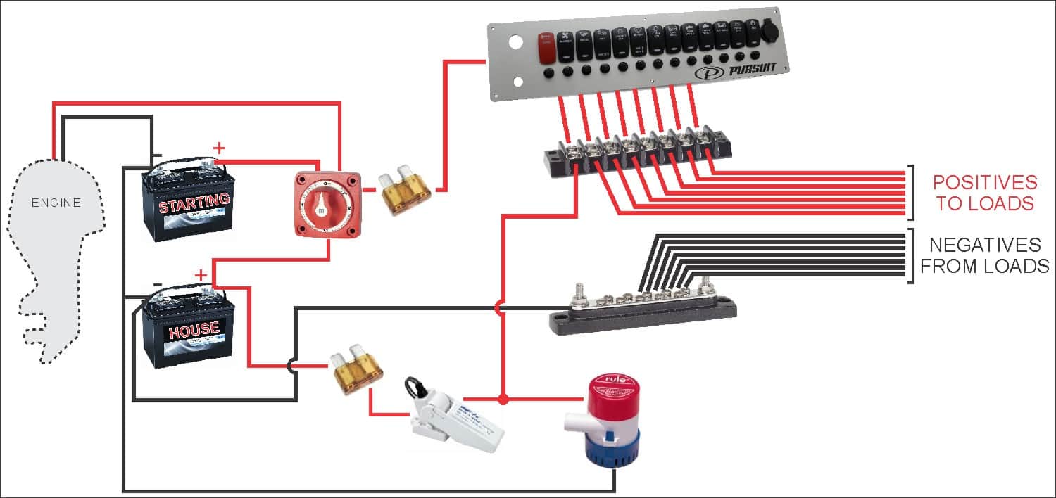
Here is a tabbed step-by-step diagram for how to wire a boat
Battery switch, bilge float switch, main feeders, terminal block, load wiring, dig our boat wiring content.
We’ve got lots more cool boat wiring stuff to share!
Signup below for the occasional interesting – not spammy – Boat Wiring tip email, and we’ll email you our complete 13-Page PDF with a bunch of schematics, tips, tricks and checklists to help with your re-wire project, and beyond!


14 Steps To Wiring Your Boat
What you need to know to install or re-wire the electrical system on your boat. a step-by-step practical guide. covers planning, diagrams, wiring, batteries, over current protection and more..
I want to thank Ed Sherman for reviewing this page for accuracy.
A question often asked on boating and boat building forums, and by visitors to my web site, is: “I need a simple wiring diagram for a small outboard boat to wire up the lights and few other things, but no one seems to have one. Is there one, and where can I find it? Are there a set of step-by-step instructions?”
There are wiring diagrams, websites and forums that tell you how to wire an electrical system for large boats and bigger sailboats. But when it comes to small boats there is a distinct lack of information and diagrams for how to install a simple, safe, and reliable electrical system.
The following is meant to apply only to small outboard boats under 16 feet with 50 or 60 horsepower or less. It can be applied to slightly larger boats that have a simple 12V DC system using one or two 12V batteries.
Note 1 : I will not deal with the wiring specifically for the outboard motor and controls. Here is a web site where you can obtain wiring diagrams for most outboard motors. Most new outboards come with a wiring harness and a manual that has wiring diagrams. See Master Tech Marine Outboard Wiring Diagrams .
Note 2: If you are re-wiring a boat with an electrical system installed: Don't rip out that old system yet ! Use the old system to help make a plan in steps 1 through 7. Trace out each wire and put that on your diagram. This will make it far easier to locate wires and equipment. Wait until you actually start installing wiring in step 12. Then replace each set of wires with new. This may take a little more time, but will result in far fewer mistakes and less troubleshooting.
Note 3: Throughout this I will give references to the US Code of Federal Regulations (CFR) requirements that apply to boat manufacturers, and to the American Boat and Yacht Council industry standards. Examples: 33 CFR 183.401, or ABYC E-11. The US Coast Guard Regulations (the CFR) and the ABYC standards are good guidelines to follow for a safe and reliable electrical system. They are used by marine electricians, professional boatbuilders, designers, marine surveyors, and marine repairers. If that’s how the pros do it, so should you.
Step 1. Make a Plan. Decide what you want to install, and where it will go. See Electrical Planning
Step 2. Draw a simple electrical schematic (diagram) that shows each piece of equipment, the fuses, switches, and how all of this will be connected. This is not a diagram of where the equipment is located on the boat. That will come in Step 8. It is simply a diagram of the electrical circuits. Here are two alternative examples. (Click on the diagram to expand.) The first diagram uses a positive buss bar. The second omits the positive buss bar. For clarity I did not use color codes except red (positive) and black (negative).
Do not be concerned if you don’t know electrical symbols. Just make a box or circle and write in what it is, or you can use a picture of the item. As long as you understand what goes where, and how they are connected, it’s Ok. Remember, any 12V DC device must have at least a positive and negative wire connected to it. Put a plus or minus next to the wire or use red for positive and black for negative. On metal boats do not use the hull as a return (negative) path. Connecting your electrical system to a metal hull can result in stray current corrosion.
See also BoatUS diagram:
There are several ways to draw wiring diagrams. The most important thing is that you understand what you are diagraming. It needs to be simple enough and clear enough for you to be able to refer to it in the future and still understand what each item is, what the wiring is and how each item of equipment is connected to the electrical system. That way, in the future if you want to add or subtract equipment you can do so by referring to your diagram and determining where and how the new item fits into the system.
Step 3. Batteries: Decide where you will put the battery. Later we will decide the capacity and type of battery but for now we only need to decide where to put it.
The battery is the source of power for starting, instrumentation, and lighting. There may be a second battery on some boats for running a trolling motor or other equipment.
Batteries should not be too close to anything that can cause an accidental short. There should be 12 inches of space all around them. Batteries must not be directly under or over fuel lines or under other electrical equipment such as a charger or inverter. If they are, there must be a floor or panel separating them. ABYC E-10.7.5 and 10.7.6 Storage Batteries
Batteries need to be in a space that is ventilated to the atmosphere. 33 CFR 183.420(e) This applies to all batteries, not just lead/acid batteries.
Batteries must not move, so they have to be fastened down. 33 CFR 183.420(a)
There should be a tray under a battery for spilled electrolyte, or it should be in a battery box, and fastened down so it won’t move under any conditions. (ABYC E-10.7.2) The Coast Guard does not require a tray or a battery box but ABYC does require some means to contain spills. If it is strapped down in a tray, spilled acid won’t damage the boat and the battery won’t move. The terminals need to be covered with a boot or some other device that protects them from accidental contact with metal tools. But, if the battery is in a box the terminals are protected against accidental contact with tools, spills are contained, and it won’t move.
The battery should be close to the engine. Since starting current is so high, and the wires to the starter are not fused, you want to keep the wires as short as is practical.
The battery should be a combo starting/deep cycle battery, usually sold as a marine battery. An auto battery would do for starting and lights. But, for running a radio, and other electronics while anchored or fishing, a battery with a little deep cycle capacity is needed so the battery doesn’t go flat and leave you stranded when you try to restart the engine.
How big a battery (capacity, not physical size) do you need? That depends on the amount of load on the battery. I will show how to determine that in Step 12.
There is one non-electrical consideration; weight. Lead acid batteries can weigh up to 50 lb. Think about how the weight of the battery will affect weight distribution on your boat, especially if it is on the same side as the helm and controls. You may have to move it to balance the boat side to side. If you have a very low transom, how will the weight of the battery affect the water line at the transom?
Step 4. Battery Switch: Some people think that a battery switch is not necessary on a small boat. I think a battery switch is necessary to turn everything off when you are not using the boat.
Where the battery is located determines where the battery switch goes. It should be close to the battery but easily accessible to be switched off in an emergency. ABYC E-11.6.2.
A good brand is Perko but there are others. Avoid any battery switch that is not UL Marine Listed. There are cheap ones on the market that are not UL listed and can get hot and melt.
A battery switch must be ignition protected. (33 CFR 183.410)
Ignition protection means that it will not ignite gas fumes if they are present. This is extremely important if you have a gasoline fuel tank in the same compartment as the battery.
Use only ignition protected electrical components. You don't want anything in there that will set fuel vapors off. Batteries are not considered a source of ignition because there are no moving parts, but if you make accidental contact with metal tools it can create an arc. So, the terminals must be protected, and battery switches and other electrical equipment in this compartment must be ignition protected.
Buy a switch that has a provision for two batteries because you may want to add a battery in the future. The switch will have three positions. OFF, 1, 2, and BOTH. The 1 position connects the one battery and allows charging of that battery when the engine is running (if your outboard is large enough to have an alternator). The 2 position connects and charges the second battery, if there is one, and the BOTH position puts the two batteries in parallel doubling the battery capacity and charging both at the same time. You won’t need the BOTH and 2 positions now, but this gives you the option to add a second battery.
Step 5. Fuses: Next, install a fuse block close to the battery switch. Fuses must be within seven inches of the source of power (33 CFR 183.455) but you can go up to forty inches if the wire is sheathed. Standard wire loom is fine as a sheath. Be aware, the fuse is there to protect the wire, not the equipment. If you overload wiring it gets hot, melts and starts a fire. We will determine the size of the fuse later. See Step 12. Buy a fuse block with two fuse holders. That way you have a spare if the fuse blows. This is generally a good idea. When installing fuse blocks get ones with more fuse holders than you think you need. You will need them eventually. One or two extra fuse holders is good.
Step 6. Equipment Location: Determine where each piece of equipment will be.
Think about where you want things to go. Depth finders need to be where they are easy to see, but not blocking your vision when operating the boat. Radios should be where they can be easily reached, and for VHF, reach the mike. The back of the console or surface you are mounting them on needs to be easily accessible for access to the wiring.
Step 7 . Locate the fuses, buss bars and switch panels.
Decide where to put fuse boxes, buss bars, switch panels, etc. Each of these must be close to the equipment they power, and easily accessible to be worked on. They cannot be hidden behind equipment or inaccessible panels. This may sound obvious, but I have seen some very bad installations. Also, they should be protected from spray or rain.
Most electrical and electronic equipment comes with pigtails. Pigtails are wires coming out of the equipment and may only be a few inches to several feet long. Sometimes they have a connector attached to the ends of the wire. When determining where stuff goes consider the length of the pigtails, because you don’t want a rat’s nest of wires hanging loose.
Switch boxes: A box or panel where switches can be mounted to control stuff. On a small outboard boat this is usually the dash or the console.
Fuse block: A panel with fuse sockets on it. It can be open or covered.
Buss bar: A block with studs for connecting wires.
Typical Buss Bar: This buss bar is for the negative wires. The large wire on the left is the battery negative.
There are some devices that are connected directly to the source of power and do not go through fuse blocks and switches. They need to always have power. One is the bilge pump. Bilge pumps may have a float switch that automatically turns the pump on when water in the bilge gets to a preset height. This won’t work if the pump is not wired directly to the battery. It is not good practice to wire it directly to the battery though. Wire it to the power input side of the battery switch. It is good to install a switch at the helm that turns the pump on manually.
If your boat has an anchor light, you may also want to wire the switch for the light directly to the power input side of the battery switch. That way you can turn on the anchor light when the battery switch is off.
Step 8. Make a diagram of the boat showing where the wiring, equipment and fuse blocks will be located.
Make a rough drawing of the boat looking down from the top. This is called a general arrangement and shows how the boat is laid out. Using your electrical schematic, put in where the equipment, fuse boxes, buss bars, switch boxes and wiring are going to go. Check this against the actual boat to make sure you aren’t missing something.
Wiring cannot go through pieces of equipment, pipes, tubes, and other solid objects. They can go through walls and bulkheads and panels. Wiring must be easily accessible for installation, trouble shooting and replacement. It must be fastened down at least every 18 inches (ABYC 11.15.4.1.9) so it isn’t or chafing on something. Where wiring goes through a bulkhead, wall or panel, it must have a grommet or padding to protect the wire. 33 CFR 183.445(a)
Your diagram may look something like this; (Click on image to expand)

Step 9. Wiring: Figure out how much wire you need, what size wire you need, and what color it should be. Wire standards.
What about the wires from the battery Switch to the starter? The wire needs to be a very heavy gauge, at least a 4 AWG on small outboard boats, because starters draw a lot of current. Both the positive and negative wires should be the same size. If the outboard has the wires for the starter already installed, the wires from the battery to the switch should be the same size as those wires. The engine manufacturer has determined the amount of amperage the starter draws and correctly sized the wires for the load.
The positive wire (red) goes from the battery to the input side of the battery switch. The negative (black) wire goes to a buss bar. One post on the buss is for the wire from battery to the engine block (ground). Another wire goes from the buss up forward to the dash. The others are for other equipment. There should be as many terminal posts as you need plus a few extra.
Color Codes: The positive wire should be red. Negative can be black, or yellow, or black with a yellow stripe. Throughout the boat negative wires should be black or yellow or a combination. AT the dash or console, all positive wires from the fuse block to the instruments and the equipment, should be color coded using the standard color codes for marine wiring. Direct Current Color Codes: From ABYC E-11.15.2.3 Table 11 and Table 12.
Direct Current Color Codes: From ABYC E-11.15.2.3 Table 11 and Table 12.
Color codes tell you what the wire is for. But label the wire on both ends. A simple piece of tape with a name written on it will do. They do not need to be fancy labels, but if you prefer, you can buy labels at electrical suppliers or hardware stores.
Wire must be marine wire. (33 CFR Sec. 183.435) Do not use auto wire. It is not made to the same standards as marine. Most marine wire is labeled UL 1426. It must be copper stranded wire. It does not have to be tinned, although tinned wire will last longer. On a small boat it is not necessary. Do not scrimp on wire though! Cheap wire could mean the difference between a reliable system and one that you constantly have trouble with. Buy good quality wire. I have seen 100 ft spools of Ancor 16 AWG Tinned Marine Wire for sale on-line for as little as $24.00 USD.
What size wire? American Wire Gauge (AWG) is in reverse order. The larger the number, the thinner the wire. The thickest wires are 00 or 0 AWG. The smallest gauge allowed on boats for a single wire is 16 AWG, or 18 AWG if it’s in a bundle or sheath (33CFR 183.425), but this may be way too thin for the equipment or the length of the wire run. The only exception to this is wire inside electronic devices or part of the electronic controls on the engine. 33 CFR 183.425(g)
The thicker a wire is, the less resistance it has. The longer a wire is the more resistance it has, and so there is a larger voltage drop. You want to minimize the resistance and the voltage drop. So you first need to figure out the wire size based on how many amps are being used, and then by how long the wire is. Use the tables in Appendix A, at the end of this page, to determine the correct size. Don't just guess at wire size and buy larger diameter wire such as 14 or 12 AWG. See Wire Size:
For the purpose of determining wire size, the fuse block the wire is coming from is considered the source of power. For the wires running from the battery to the starter, or to the under-dash fuse block, the battery is the source of power. In the two examples below the fuse block under the dash or console is the source of power.
Here is an example:
A Hummingbird Model 345C depth sounder draws 380ma (milliamps from the specifications). The installation includes a 6 foot power cable of 18 AWG wire. This may be fine for connecting it to a fuse block near the dash. But we need to size the cable running from the battery to the dash. It is going to be at least 10-12 feet long on a 16 foot boat. Double that length for the negative return wire.
Use table 3 in The Appendix for voltage drop. Most boat manufactures use wire rated for 105C (degrees Celsius - the temperature rating of the insulation on the wire). Looking at the table under the column for 105C we see amperages starting at 20 amps, 25 amps, 30 amps, and so on. Following the row for 20 amps to the left column we find 18 AWG.
From the table on voltage drop an 18 AWG wire 20-24 feet long (30 feet in the table) with a 15-ampere load will have less than a 10% voltage drop. But it can only be 18 if it’s in a sheath or bundle. So go up one size to 16 AWG.
Another Example:
Suppose I have three electronics running off a fuse block in the dash or console. Each piece of equipment requires 1 amp at 12 volts to run. The total amperage for the three items is 3 amps. From the fuse block in the dash or console to each item of equipment, there is a positive wire from the fuse to the equipment, and a negative wire running back to the buss. Using 1 ampere, we determine the size the wire should be, by using table 1 and 3 in Appendix A. For instance, if the positive wire is two feet long then the total length of positive and negative wires is 4 feet. Looking at the Table 1, the line for 18 AWG wire at 105C allows up to 20 amps.
So, we could use 18 AWG. Look at Table 3. We see that an 18 AWG wire, 10 feet long, will have less than a 10% voltage drop for up to 5 amperes. Again, we could use 18 AWG but since 18 AWG wire has to be in a bundle or a sheath we add a level of safety by using 16 AWG.
This is done using the tables developed by the US Coast Guard and ABYC. You don’t have to know any formulas to figure it out. The first table determines the wire size based on the load in amps and the second table the size depending on length and voltage drop. You use the larger wire if there is a difference.
See the table in Appendix A at the bottom of this page. or ELECTRICAL TABLE: 33 CFR 183.42: ALLOWABLE AMPERAGE OF CONDUCTORS FOR UNDER 50 VOLTS or: ELECTRICAL SYSTEMS VOLTAGE DROP
Step 10. Wiring tools. Wire connections (terminals). See Connectors :
Tools: Use good quality tools, especially good quality crimpers and wire strippers. Cheap crimpers make bad crimps. Bad crimps make bad connections. Poor wire strippers nick the metal conductor which may cause the wire to break or have a high resistance. See My Page on Practical:
Wire terminals must be used . Connections should never be a bare wire wrapped around a stud or post. This is bad practice, and can easily come loose or result in a high resistance connection. High resistance equals heat, which results in fire. Never use wire nuts to connect wires on a boat! They are prone to vibration and corrosion. ABYC E-11.15.3.7 Twist-on connectors (i.e., wire nuts) shall not be used.
Use crimp type ring or captive spade terminals. Captive spade terminals have a tang on the ends. This prevents them from being pulled off or slipping off the stud or post. Connections must resist being pulled off. In the ABYC wire standard there is a table listing how much of a pull they must withstand depending on the size of the wire. A 16 AWG wire must withstand a ten lb. pull. A 4 AWG wire must withstand a 70lb pull.
You can solder connections if you like but crimp them first . ABYC standards do not prohibit soldering, but they do not allow soldering to be the sole source of support for the connection. (ABYC E-11.5.3.8) This is because solder creates a hard spot in the wire which is not as flexible as the wire itself and not as resistant to flexing and vibration. So, if you solder you must also crimp. Crimp first, then solder.
Seal wire connections with a good waterproof sealant , usually marketed as dielectric grease. There is no requirement to do this, but it prevents water from getting in the connection and wicking up the inside of the wire insulation or corroding the connector.
My method. I do not solder. First I slide a short length of heat shrink tubing onto the wire. https://en.wikipedia.org/wiki/Heat-shrink_tubing How long it is depends on the wire and connector size. Usually if the tubing extends about 1/2 inch (1 centimeter) beyond the end of the connector, that is enough. Then I use dielectric grease. See Wikipedia on Dielectric grease . Dielectric grease is non-conductive grease, usually silicone that is also waterproof and can be used to seal connectors. Before crimping the wire in the connector, I squirt a little dielectric grease into the connector where the wire goes. I then insert the wire and crimp it. Then I slide the tubing down over the connector and shrink it with a heat gun or hair drier so it seals itself around the wire and connector. The combination of grease and heat shrink tubing should keep the water out.
Heat Shrink Tubing And Connectors, AAA protection, How to install and repair. http://youtu.be/jCRsx38WRw8
How to get a good crimp: Marine How to: Wire terminations: https://marinehowto.com/marine-wire-termination/
Step 11. Fuses . How big should your fuses be?
Fuses are rated by amperage and protect the wire from overheating and fire. Fuses must be rated at the same or less rating of the wire. If you have a wire that is rated at 15 amps you need a 15 amp fuse. Each circuit is rated for a certain amperage, such as 15 amps or 20 amps, and more equipment is not added to the circuit if it would cause it to draw more current than the fuse is rated for.
This can become an issue on little boats too if you have more equipment, or something like a powerful stereo system that draws a lot of amperage. Then it should have its own circuit and its own fuse for the circuit.
The question is how many fuses in the block? That depends on how much stuff you are running. I would have a fuse for the lights, one for the instrumentation, and one for any electronic devices, plus a spare. That is four. But for expansion maybe a six or 8 fuse block would be better. Again, in the future you won’t have to buy a new block. See Overcurrent Protection:
Step 12. Installing equipment .
Start with the battery, the battery switch, and the main fuse block.
Selecting a Battery: Batteries are rated by voltage and capacity. We are using a 12V battery. There are two ratings, CCA and MCA See Batteries at:
CCA Means Cold Cranking Amps. MCA means Marine Cranking Amps. These are measures of how many amps the battery can deliver for 30 seconds and maintain the voltage at 12V. Basically the higher the CCA rating the longer the battery will maintain its voltage. Batteries are also rated by amp-hours. 1 amp for 1 hour is 1 amp-hr. Generally the rating is based on how many amps the battery will discharge for 20 hours until the charge drops to 10.5 volts. The higher the amp hour rating, the longer the battery will power your equipment. Also, batteries are rated for Reserve Capacity which is how many minutes it will deliver the same voltage at 80 degrees. An average marine battery should have a Reserve Capacity of 60 to 90 minutes. Anything less is not adequate.
There are four types of batteries commonly used on boats, Wet Cell (also called lead acid, flooded, or flooded lead acid, and sometimes abbreviated FLA), AGM (Absorbed Glass Mat, Gel, and Lithium, but for now I’ll stick with the standard wet-cell battery. They are relatively inexpensive, can be purchased anywhere, and for a small boat, more than adequate. A battery with a CCA or MCA rating of 200-300 should do but we’ll determine that when we calculate the loads. See table below on how to calculate loads. Battery Capacity should be at least twice the load.
To calculate loads, list the equipment you are planning on installing. In the chart below the following items are listed. Navigation lights Bilge Pump Radio (Only when receiving) Depth Sounder engine electrical Instruments GPS Bait well pump Horn Radio TX. (VHF Marine radio. It draws more when transmitting)
Determine from the specifications for each item what the current load is in amps. Separate them into continuous loads (on all the time) and intermittent loads (only on when used). Determine how many hours they will be used. Multiply the amps times the hours to get amp hours. Add up the amp hours.
See Also Electrical Planning
Double the result to determine what the rating of the battery should be. For this case, 200.
Another consideration is the battery group size. Batteries come in different physical sizes. A Group 24 battery is 10 ¼ inches by 6 13/16 inches by 8 7/8 inches. A Group 27 battery is 12 1/6 inches by 6 13/16 by 8 7/8 inches. The physical size is determined mainly by how much space you have for the battery and its weight. A bigger battery weighs more. A large group size does not necessarily mean it will last longer. That is determined by the battery ratings for amp hours and reserve capacity. The most commonly used size on small boats is Group 27.
Install the battery box if you are using one, or a tray, then the battery. Now that you have installed a battery you can begin installing equipment. Install lights and electronic equipment. You want everything in place before you begin wiring. Put in switch panels and fuse blocks.
From Step 5. We need to determine the size of the main fuse at the battery. The continuous loads add up to 10.5 amps. The fuse in a DC circuit should be about 150% of the load so a 15 amp would be appropriate. (ABYC E-11.10.1.5.)
The fuses for each circuit of our example should be at least 3 amps except for the VHF radio because on transmit it draws 6 amps. So, use a 10 amp fuse for the radio circuit. Check the manufacturer's installation instructions for recommended fuse sizes for each piece of equipment. Remember, this fuse is to protect the wire to the equipment, not the equipment. Some equipment may have built in or in-line fuses for that purpose.
Step 13. Installing Wire:
Begin installing wire, starting at the battery and working outward to each fuse block and buss bar, and then on to each piece of equipment. Remember to follow the color codes and label the wires on both ends. If you decide to make any variations from your diagrams make sure you change the diagram for future reference.
Step 14. Turn on the power. Test by turning on each item, one at a time, to see if it works. Troubleshoot as you go. If there is a problem, fix it before you proceed. Once everything has been tested individually, turn on everything, one at a time, until everything is on. If a fuse blows or something doesn’t work the last item you turned on is where the problem lies. Turn everything off, fix it and then try again from the beginning.
An Excellent Article: Avoiding Boat Electrical Mistakes by Ed Sherman; Boat US Magazine https://www.boatus.com/expert-advice/expert-advice-archive/2016/august/avoiding-boat-electrical-mistakes
An excellent article by Owen Youngblood on Wiring Your Boat , from the Metal Boat Quarterly
How to Wire A Boat from New Wire Marine https://newwiremarine.com/how-to/wiring-a-boat/
The USCG Boat Builders Handbook for Electrical Systems is available on-line at https://safeafloat.com/wp-content/uploads/2021/04/I-Electrical-Systems-Final-4-14.pdf
Contact ABYC for a copy of E-11, AC and DC Electrical Systems on Boats. There is a fee. See: https://abycinc.org
Appendix A: Allowable Amperage and Voltage Drop Tables
Note: This is the table that is in the Federal Regulations. The Federal Regulation now uses the ABYC table. It is published in 33 CFR Subpart I sec 183.425. ABYC Standard E-11 has five separate tables based on how many conductors are in a wire bundle.
The table for voltage drop is below. This is only for 12V DC. Contact ABYC for a copy of E-11, AC and DC Electrical Systems on Boats. There is a fee. See: https://abycinc.org
This is the table to determine wire size due to voltage drop based on the length of the wire. This table is for 12 volts only. The top row is the length of the wire in feet. The first column below Total Amps, is the amount of maximum amperage. The number in the row to the right of the total Amps column, is the size of the wire for a 10% or less voltage drop. Example: 25 feet of wire (top row) at 15 amps (first column) the wire would be 14 AWG.
Navigation Lights: I added this section because many people asked for it.
Wiring Navigation Lights for boats with combination red/green bow lights and an anchor/sternlight on a pole. I have been asked many times if there is a standard wiring diagram for hooking up the lights on a small outboard or inboard boat. There are some variations on this but here is how I did it on my boat.
The below diagram is for small boats with a red/green combo light on the bow, and a single sternlight that can also be used as an anchor light. Usually these have a single switch with 3 positions; Off, 1. anchor light, 2. combo bow light, sternlight/anchor light, and instrument lights. The diagram shows a Cole-Hersee switch that is in common use, but there are other manufacturers that also make switches for this, such as BEM and Blue Seas. They all serve the same function. In this diagram the lights are wired directly to the battery. However, some people prefer to wire it through the battery switch so the battery is not discharged if the lights are accidentally left on. It is just a matter of switching the power wire from B on the lights switch, to the number one position on the battery switch.

© newboatbuilders.com 2007 All rights reserved. revised 03/17/2023
Created with Dreamweaver 21.2 ©newboatbuilders.com 2022 All Rights Reserved
Are Your Boat Electrics
Safe & reliable, ...or do they look like this:.
- Your boat's electrics are a "black box" to you?
- You are worried that parts of your system might fail?
- You want to upgrade or install new equipment in a professional manner?
Sounds familiar?
We teach you how to install and maintain a dc system on a boat like a pro, boat electrics 101 , safe & reliable dc systems, your teachers.

Nigel Calder

Dr. Jan C. Athenstädt

Michael Herrmann
We are Nigel, Jan & Michael. We help you understand, extend, and redo your boat electrics. The right way.
I now understand all the electrical systems and how everything works together.
Bob russell - s/v spartina.
Jan, Nigel & Michael, I want to let you know how impressed I was with the BoatHowTo course !! Having purchased a new to me Island Packet 350 this year, I was overwhelmed with all electrical systems on the boat! Modern cursing boats have become very complex and I was lost! Having taken your Boat Electrics 101 course I now understand all the electrical systems and how everything works together . From the very basics, through creating a detailed circuit diagrams of the electrical systems on my boat, my knowledge is years ahead of where I thought it would be at this point. Thanks for a wonderful, extremely useful (and fun) course that takes a lot of the mystery out of sailboat electrical systems!!
Boat electrics is not rocket science ... ...but it still has to be DONE RIGHT !
Electrical systems on boats have become more and more complex over recent years.
Even moderately equipped boats today rely completely on their electrical system . A loss of power means in most cases an emergency at sea. (Or do you still have a sextant and all nautical almanacs on board?)

Boat electrics are often poorly understood, despite being such a vital part of the operation of a boat.
The good news: It's not that hard!
With a bit of time and a commitment to learning, everybody who mastered basic high-school math and physics will be able to understand the DC system on a boat. All it takes is a reliable and easy to understand source of information .
You want to understand your system?
Clearly expressed and illustrated, the course is full of practical information, derek nowek - falmouth, me.
The Boat Electrics 101 course is a fantastic resource for beginners like myself who know little about electricity and even less about boats electrical systems. Clearly expressed and illustrated, the course is full of practical information presented in a way that makes boat electrical systems understandable. Thank you for putting it together.
The majority of fires that start on boats are caused by the electrical system !

Understanding your boat's DC system can significantly improve the safety of your boat!
Unfortunately, many owners have only a vague understanding of their boat's electrical system. Or, even worse: They think they know how to install a system and end up making damaging mistakes...
...and teach others these mistakes in blogs or on YouTube.

YouTube is full of videos about Boat Electrics
– many are wrong and some are dangerous.
The internet is a great source of information. And in recent years, many people have shared their experience installing or fixing electrical problems on their boats.
The problem: Many of those people are not professionals!
It's easy to put a professionally looking video on YouTube...
...but it is hard to tell, if this actually is professional advice - or misleading BS.
If you follow bad advice on how to varnish teak and you end up with a mess, in the worst case you lose time and a bit of money.
If you follow bad advice on how to connect batteries and your boat ends up in flames, this is a different story.

A typical example of bad advice...

...is soldering. Soldering is often praised as a great way of connecting wires. On a boat, it is not. Soldered connections are rigid and tend to break when exposed to the vibrations common on boats.
This is why electrical installation standards from the American Boat and Yacht Council (ABYC) and the European International Organization for Standardization (ISO) both explicitly prohibit soldering as the only means of connection!
You want know how to do it right?
Your brand new boat is properly wired..., ...or maybe not.
When visiting boat shows, Nigel likes to inspect the electrical systems on brand new boats . Unfortunately, this has become quite frustrating: a shockingly high number of production boats come with badly installed electrics – straight from the boatyard.

These batteries were installed on a brand new boat. What's wrong here?
- Inadequate support against sliding off the shelf
- Parallel connections badly designed - this will lead to premature battery death
- Too many cables on the positive battery post
- No overcurrent protection devices anywhere near the positive battery pole
This installation might look neat at first glance. But:
It is unprofessional and asking for trouble!
You want to assess your system, i now feel empowered to research and undertake this work on my own., mark sweetnam - ireland.
Wow, what an outstanding course – thank you so much. I intensively studied each lesson, took notes (frequently pausing the video to do so), read and made sure I fully understood the lecture notes and then likewise all comments. The entire course took me about 6 full days to complete. In my own case I have owned a 30 year old Swedish boat (Najad) for the past 10 years. It has both 12V and 24V house systems, with two alternators. I got the batteries replaced about 8 years ago (with Victron AGM) but am now looking to upgrade the electrics in numerous ways, and obviously to audit and rectify any OCP or other shortcomings. New batteries will obviously be needed shortly but I also want to add solar. But mainly I want to either get rid of the 12V bank (and use DC-DC converters for the 12V house load) or add 12V-24V-B2B charging both for redundancy and to use full capacity of both 12V and 24V alternators and shore power battery chargers. I now feel empowered to research and undertake this work on my own. Thanks again.
Who or what are ABYC and ISO ?
The ABYC E-11 and the ISO 13297 standards cover the principal electrical systems on small craft.
Even though they are legally non-binding, they are based on decades of experience of hundreds of experts in the field.
So, instead of trying to figure things out for yourself (with potentially disastrous consequences), it is a good idea to follow these standards as closely as possible.

All three of us are members of various standards committees of the ABYC and ISO, Nigel and Michael for decades. Everything we teach at B OAT H OW T O is compliant with ABYC and ISO standards.
There is no one who knows the standards better than us.
The American Boat & Yacht Council (ABYC) is a non-profit, member organization that develops voluntary global safety standards for the design, construction, maintenance, and repair of recreational boats. As an independent consensus-based body, the industry experts at the ABYC (including Nigel Calder from B OAT H OW T O ) work together with the sole purpose of protecting the safety of the boating public.
The ABYC’s Standards and Technical Information Reports for Small Craft cover all major boat systems. The development and regular review of these standards provide boat building guidelines that correlate directly with a significant reduction in the number of boating accidents over the past six decades.
The International Organization for Standardization (ISO) develops high quality voluntary International Standards. The sub-group of the ISO that addresses small craft (up to 24m/70 feet), is known as Technical Committee (TC)188 (of which Michael Herrmann and Jan Athenstädt from B OAT H OW T O are both members). This committee has developed a set of standards that are closely aligned with the ABYC standards.
With respect to boat electrical systems the principal difference between the ABYC and ISO standards lies in the fact that the ABYC standards tend to be more detailed. In order to provide the most detailed information in our lessons, we follow the ABYC standards. Where there are minor disagreements with the ISO (only a handful) we point these out.
You want your electrics to comply with ISO & ABYC standards?
We know what we are talking about..., ...and how to apply this knowledge..
Understand the basics of a safe and troublefree installation. Learn how to plan and design a system. Get practical advice on how to put everything in place.
Understand the basics of electrics in general and boat electrics in particular
Learn how to assess existing systems and how to (re-)design the wiring of your boat
Get your hands dirty with practical advice on how to crimp wires, install batteries and much more
The course has given me the knowledge to make better choices
Tommy kaine - sv alboe.
Just a note to say how terrific the Boat Electronics 101 course is. It is very comprehensive. It has empowered me to refit my 1976 Westsail 32 original electrical system. Though I am outsourcing some of the work, the course has given me the knowledge to make better choices, do my portion of the project, and have a smart conversation with the contractors. Thanks for all your hard work and keep it up!
Good marine electricians are rare...
...and expensive, so why not learn how to do it yourself.
Instead of paying hundreds of dollars for a few hours of advice and help from a marine electrician, you can invest in your knowledge - and become more self-reliant!
With our help you can learn how to operate, maintain and extend your boat's electrical system in a professional manner. Better than many people who do this for a living!

Invest in your knowledge and self reliance
Even if you know a good marine electrician: You will still have to deal with problems on your own as soon as you are away from the dock.
Proper preparation is key to good seamanship.
Stop worrying about potential hidden failures in your system. Empower yourself by uncovering the secrets of your boat's electrical system. Regain control in the complex world of marine electrics.
B OAT H OW T O helps you spend a carefree and relaxed time on the water. Boating or sailing the way it's meant to be.
Join us for our ONLINE COURSE on DC Systems:
B oat h ow t o boat electrics 101.
Set up a safe and reliable DC system on your boat that complies with ABYC and ISO standards.
- 1 Fundamentals: Understand the basics of electricity, how common components work and how to connect them.
- 2 Batteries & Charging: How do lead-acid batteries work and how to charge them to double or triple their lifetime?
- 3 System Design: Step-by-Step guide to plan and install a DC-System on your boat.
In 8 modules (plus bonus lessons & videos), you will learn everything from the basics of electricity to designing a whole DC system on your own.

Boat Electrics 101 - Course Contents
59 easy to follow video lessons will turn you from beginner to expert. .
Take a look at the course syllabus:
Introduction
About Boat Electrics 101
A quick welcome and introduction of your teachers and a few words on who this course is for and what to expect.
Course Structure & Overview
Get an overview on the contents of this course and the underlying standards.
Safety Precautions
In this lesson we will cover some dangers and necessary safety precautions to keep in mind before working on your system.
Electricity
Get to know the basics of electricity and learn about Volts, Amps, Ohms and how they relate to each other.
What is electricity?
What is electricity and what happens when a current flows? We take a quick look at the behavior of electrons inside metallic conductors.
Voltage, Current & Resistance
Learn all you need to know about voltage, the equivalent to pressure in electrical systems.
Ohm's law allows you to calculate how resistance affects voltage given a certain current and vice versa.
Power, Energy, Consumption & Capacity
Power the product of voltage and current. With two examples you will learn how to calculate the power draw of an appliance.
A quick recap on everything we have learned so far.
End-of-Module Quiz
Test your knowledge with a quiz!
Electrical Components and Circuit diagrams
Get to know the most common components of a boat's electrical system and learn how they can be represented in a circuit diagram.
The Idea Behind a Circuit Diagram
Learn why it is important to be able to read and draw circuit diagrams.
Wires & Conductors
In this lesson you learn the symbols for wires and conductors and and their connections.
Circuit Ground
What is ground/earth and how is it represented in circuit diagrams?
Switches, Buttons & Relays
Get to know the basic symbols for switches and buttons and learn how relays and solenoids work.
Resistors & Shunts
Get to know the symbols for resistors and learn about the most common type of resistor on board: the shunt.
Fuses & Circuit Breakers
How are fuses and circuit breakers represented in circuit diagrams?
Coils & Transformers
Coils mostly occur on boats within transformers. Here you will learn about their basic function and how to represent them.
Lamps, LEDs, Diodes, etc.
In this lesson you will get to know a few more symbols for common components in a boat's electrical system.
Basic Circuits
In the final lesson of the module, you will learn how the components in boat electrics are connected in parallel and in series and how this affects battery capacity and voltage.
Test your knowledge with a Quiz!
Conductor Selection and Installation
In this module, you will learn how to choose the right type and size of conductor and how to properly install it. This is crucial knowledge for anyone planning any modification on their boat's electrical system.
Conductor Construction
Learn about different types of conductors and which ones are suitable for use on boats.
Colors & Labeling
Learn what conductor colors you can use for what purpose and how to properly label your wiring.
Sizing Conductors
Learn how to choose the proper size for a cable with respect to ampacity and voltage drop.
Terminals & Terminal Installation
It is crucial for the system's safety to establish proper connections. In this lesson you will learn how to install terminals in a professional manner.
Making the Connection
Proper connections of terminals to bus bars and consumers are vital. Here you learn what makes a professional connection.
Overcurrent Protection (OCP)
In order to prevent fires due to overcurrents and short circuits, protective measures are absolutely crucial. In this lesson you will learn how to choose fuses and circuit breakers and where to install them.
Conductor Installation
Learn the proper way to install conductors in order to protect them from chafing and physical stress
Case Study: High Output Alternators
In this lesson we will apply what we have learned in this module to the special case of high output alternators. As we will see, there are quite a lot of things to consider.
Bonus: Nigel’s Examples
Here we show a few more examples of good or bad installations and also what happens in case of a short circuit if no adequate OCP is installed.
In this module we cover all you need to know about lead acid batteries.
Get an overview on what to expect in this important module.
Battery Safety
Even though they operate at relatively low voltages, there are significant dangers when dealing with batteries. In this lesson we cover the required safety measures.
Lead-Acid Battery Chemistry
In this lesson you will get an overview on the chemistry inside a battery and how lead acid batteries work.
Battery Construction
Here we go more into the details of the internal construction and discuss the differences between cranking and deep cycle batteries.
Battery Types
Now it's time to look at different types of lead acid batteries, such as wet cell, AGM, gel-cell and some new innovations.
Battery Efficiency
Learn about the crucial difference between amp-hour and watt-hour efficiency and how to evaluate batteries based on this.
Battery Ratings
What do the common ratings found batteries (nominal voltage, nominal capacity and cold cranking amp) mean?
Battery Failure Modes
In this lesson you will learn what the most common reasons for battery failure or reduced lifespan are and how to avoid them.
Series & Parallel Batteries
Learn how to maximize battery life when installing batteries in serial or parallel.
Sizing Battery Banks
This lesson will help you decide how much battery capacity you really need for reliable operation and optimal battery lifespan.
Lead-Acid Battery Installation and Maintenance
Learn how to properly install your battery bank and how to maintain it in order to optimize its performance.
Charging Systems
In this module we cover in detail all you need to know about charging batteries. Topics include charging profiles, charging systems, charging circuits and systems monitoring.
Failure Modes Revisited & Expanded
Learn about the most common failure modes with lead acid batteries so mistakes can be avoided.
The Water Tank Analogy
Through the analogy of a water tank with semi-permeable membranes we explain why it takes a long time to completely top off a lead acid battery.
Charge Profiles
Learn what an IUoU profile is and how the bulk, absorption and float phases increase battery life.
Fast Charge & State of Charge (SOC)
Learn strategies to reduce charging times and engine hours while at the same time increasing your battery's lifespan.
Charging Devices
Learn what to look for when choosing a battery charger, an alternator or when planning on installing renewable energy sources.
Charging Circuits
Learn about different ways to charge multiple battery banks from a single power source.
Systems Monitoring
Learn about the importance (and challenges) of proper battery monitoring.
Summary: Batteries & Charging
A quick recap on what we have learned so far in this module.
Energy Systems Design
In this module we will draw on what we have learned about batteries and charging systems to design an energy system optimized for how we want to use our boat
Energy Systems Introduction
In this lesson we introduce the BoatHowTo Boat Electrics Planner which will help us to determine the energy balance on our boat
Energy Consumption
In this lesson, we will look at all loads on the boat and determine their energy consumption for different scenarios.
Energy Storage
To store the energy between charge interval, we have to carefully design our battery banks. In this lesson we look at various options for batteries depending on our calculations from the previous two lessons.
Energy Generation
Now we look at the supply side and determine the available charging sources such as shorepower chargers, alternators and renewable energy sources and their required output to keep up with our energy needs.
Case Studies: Planning a (Re-)Wiring
Now it's time to put what we have learned into practice. We show you how we would design the electrical systems for three different example boats of varying complexity.
We start the module with a brief introduction of our three example boats.
Circuit Diagrams with easyEDA
In this lesson we get to know a free, web-based tool for the creation of circuit diagrams.
Planning the Wiring
Before we get started with our examples, we examine various options for grouping loads and discuss practical limitations, in particular when it comes to older boats.
Simple Boat
We go in detail over the planning of the rewiring of our first example boat, a modest cabin cruiser for weekend getaways.
Medium Boat
In this lesson we plan the wiring of a more complex cruising boat, with systems that you can find on many medium-sized production boats today.
Complex Boat
In our third example, we use everything we learned in this course to plan the complete rewiring of a full-fledged offshore sailboat with a lot of complex, state-of-the-art systems aboard.
Final Remarks & Outlook
In this final lesson of the course, we leave you with a few final remarks. If you made it this far, congratulations! Now you should be able to assess, repair and extend your own system in a safe and reliable way and even be able to do a complete (re-)wiring job.
+ free access to the B OAT H OW T O Boat Electrics Planner spreadsheet tool + quizzes for each module to check your learning progress + exclusive bonus lessons that constantly update over time:
Bonus #1: alternative energy sources.
MODULE 1
An introduction, why it makes sense to install renewable energy sources on a boat.
Why Solar and Wind Power?
In this lesson, we explore good reasons why it might be worthwhile to install alternative energy sources on your boat.
Solar Power
MODULE 2
Solar is by far the best and cheapest way to generate energy on boats.
Turning Light into Electricity
How do solar panels work? And what current and future technologies are out there?
Efficiency Ratings and Real-World Output
What are common ways to rate solar panels and what efficiency can be expected in a real-world scenario on a boat?
Shading and Hot Spots
In this lesson we will look at the problem of shading and hot spots and how these affect the efficiency of a panel.
Solar Charge Controllers
We take a look at different types of solar charge controllers and their properties when charging batteries.
Installation Options
We take a look at various mounting and installation options for (semi-) flexible and rigid panels on board.
Wiring Sizes, Cable Connections and Deck Seals
We take a look at the wiring requirements for solar panels and the practical implementation of the wiring.
Looking Forward
A look into the future of solar technology.
A summary of what we have learned so far about solar power on boats.
Wind Generators
MODULE 3
Wind generators can help top up your batteries, but they need quite some wind to be effective.
Output of Wind Generators
We take a deeper look at ratings and efficiency of wind generators.
We look at noise issues, as these are considered one of the main issues with wind generators.
The spinning blades of a wind generator can become a serious danger. Proper mounting and installation is crucial when operating a wind generator.
Speed Control and Battery Charging
We look at options to regulate wind generator speed and battery charging.
Installation of Wind Generators
In this lesson we look at various options for mounting wind generators on a boat.
Maintenance and Disassembly
Wind generators are not maintenance free! In this lesson you will learn about common points of failure and what to look for when disassembling a unit.
Water Generators
MODULE 4
Water generators can help to generate energy when underway, but they typically only make sense on performance sailboats or catamarans.
The Idea behind Water Generators
A brief overview of technologies and use cases.
Propeller Shaft Generators
A look at shaft generators and cases in which they might be worth considering.
MODULE 5
Bonus #2: LED Lighting
LED Lights on Boats
Learn crucial things to look out for when installing LED lights on your boat.
Bonus #3: Basic Electrical Troubleshooting
Nigel’s Multimeter Talk
In this recorded presentation, Nigel explains you how to use a multimeter for simple troubleshooting tasks.
Overview & Tools
Learn which are the most common causes of electrical faults and what tools we need to trace them down.
Voltage Measurements
Voltage measurements are the most important way to trace faults. This is why this is the most extensive lesson of this module.
Resistance Measurements
If a voltage measurement does not help us track down a fault, resistance measurements might be a solution.
Current Measurements
With a clamp meter, it is possible to make current measurements without disconnecting any terminal. We show you cases when this helps with troubleshooting.
We finish the module with some tips an a brief summary.
Bonus Example: Autopilot Failure
As a bonus, Nigel explains how he troubleshooted a broken autopilot.
Bonus #4: DC Systems Design (Talk by Nigel)
DC Systems Design with Nigel Calder (IBEX talk)
In this talk, Nigel gives an overview of the challenges in designing a safe and reliable DC system. The talk was originally recorded as part of the IBEX 2021 Seminar Series.
Bonus #5: Lead Acid vs. Lithium-Ion (Talk by Nigel)
Choosing the Right Battery Technology with Nigel Calder
Nigel Calder gives an update on today's battery technology. Including important, but often overlooked, considerations on the topic of lithium-ion vs. lead-acid batteries.
It’s excellent value for money
Martin l. - .
Perhaps some might say the course isn’t particularly cheap but I would argue the cost versus the excellent work that has been done in the creation of the course and in my view at least, it’s e xcellent value for money . It is also a reminder that there are things we may think we know, until you complete the course you may well find there are things you didn’t know or had assumed differently.
So thanks for all your hard work and I do hope that many will learn better and safer ways and take a much closer look and inspection of their own electrical systems. I certainly have. There is a great deal of information to absorb and I have no doubt I will be returning again and again to re-read various sections of the course.
Ready to acquire expert knowledge in Boat Electrics?
Take advantage of our limited-time launch offer :
Immediate access to Boat Electrics 101 for only $199 instead of $299. Includes future course updates, access to bonus lessons, exclusive talks by Nigel & our Boat Electrics Planner.

60-day money back guarantee
Secure Payment
Want to learn even more? Check out our bundle offer for Boat Electrics 101 & our Advanced Marine Electrics program for just $398!
You're a professional and need CEUs or additional licenses? Choose the certificate option at the checkout to get up to 19 CEUs upon successful completion of the course! You also have the option to purchase additional licenses for your employees.
Boat Electrics 101: More Testimonials

"Boaters know there is nothing better than a trouble-free day on the water."
"Having the confidence and skills to tackle unexpected issues makes boating much more enjoyable. The team at BoatHowTo has put together a ‘Boat Electrics 101’ course designed with the recreational boater in mind. They will walk you through the skills and tools required to troubleshoot your boat’s electrical system. Each work-at-your-own-pace module will help you understand the basics, apply it to your existing system, then get your hands dirty. I always say, 'learn then do,' so we can all be safe on the water."
- Pacific Yacht Systems

"Great hands-on information for upgrading my system."
“Boat Electrics 101 helped me understand how to plan an upgrade to the energy system of our Moody 44 "High Flight". Thanks to Jan's great explanations, I am now confident to have a plan forward and make the the right choices when I will be sizing the new battery bank and upgrading the old alternator with a modern B2B charger. "
Chris Loewe
- sy high flight.

"This is the course I wish I could've had years ago! "
“This would've saved me hours of trying to figure out what the best approach is for various parts of the power setup on our Tayana 37. More importantly though, this course has given me the confidence to know that I am doing it 'right' from the start.
I've made a lot of mistakes in the past that cost me time and money, even putting the boat at risk unknowingly.
The content of Boat Electrics 101 is clear and easy to navigate. And Jan presents the content in an easy to follow (and even entertaining!) way.
I've noticed I feel less anxious, knowing better how things work and how to fix them myself. So save your time, money and stress! Invest in knowledge that will pay you back again an again as you cruise. "
Lars Sandved Smith
- navika sailing / the floating studio, meet the team:, the faces behind boat electrics 101.
Author of the famous Boatowner’s Mechanical and Electrical Manual , often referred to as the "bible for boatowners"
Nigel is a full-time sailing writer, with a focus on marine technical systems. He is often referred to as the guru when it comes to mechanical and electrical systems on boats.
His books are widely acclaimed by both boaters and professionals in the field. His most famous book, the Boatowner’s Mechanical and Electrical Manual has sold well over 300,000 copies and a staggering 4,8 stars out of 1.055 ratings on Amazon.
Besides writing books, Nigel is a long-time member of the American Boat and Yacht Council (ABYC) electrical Project Technical Committee (PTC) which writes the standards for recreational boat systems in the USA, and has also been involved in European standards development. He has recently joined marine energy systems company OceanPlanet Energy as a mechanism to continue his passion of constantly improving boat electrical systems.
Jan Athenstädt
Jan runs KlabauterKiste , a German online magazine for boatowners and KlabauterShop , an online shop for boat electrics. He holds a PhD in Computer Science.
Dr. Jan Athenstädt
Jan is the youngster in the B OAT H OW T O team. During his studies of computer science in Germany and the US, he has worked as crew on various tall ships before moving aboard his own boat.
He started teaching people how to install and maintain technical systems on their boat through his online magazine KlabauterKiste and has written articles for various magazines and online publications.
He later started an online shop for boat electric supplies which he runs from his boat while sailing the Med.
Jan is also a member of the ISO TC188 committee, helping to improve and extend the standards for electrical systems on boats.
At B OAT H OW T O he takes care of the technical side and will guide you through most of the video lessons.
Author of several books about technical equipment on boats. His book on electrical systems Elektrik auf Yachten is considered the reference for technical information in the German language.
As (now retired) founding member of BoatHowTo Michael belongs to the rare kind of people who combine a vast theoretical knowledge with the ability to apply this to the practical world.
Besides having written seven books on the topic, he has published over 500 articles in technical magazines, mainly on the topics of boat electrics and mechanics.
Since 2007, Michael has been a member of the German Boat Builders Association committee on electrics and a member of ISO TC188 establishing standards for small craft.
His latest activity in the ISO was contributing to the merger of the two basic standards for electrical systems on recreational craft - ISO 10133 and 13297.
Michael is responsible for many of the wonderful graphical illustrations we use throughout the course.
What people say about us

Nigel Calder is universally recognized as the guru of yacht systems. His hardcover tomes grace the bookshelves of yachts the world over. On Isbjorn, his are some of my most referenced books.
Andy Schell ‧ Skipper of ICEBEAR & ISBJORN at 59-north.com

I know quite a bit about boat technology. But Michael Herrmann is a living technical encyclopedia. There is definitely no question that remains unanswered. If I hit a dead end, he is my first point of contact. He simply knows everything, and if he doesn't know it he'll find it.
Christian Haschke ‧ Yacht Brokerage & Service at kornati-charter.com

Jan has a wealth of knowledge about boats and boat systems. In particular when it comes to electrics, his online shop made him a great advisor regarding the choice of the right components and their proper installation.
Laura Secorun ‧ Managing Director at ona ocean
Is Boat Electrics 101 really for me?
Unless you are already deeply familiar with the ISO 13297 or ABYC E-11 and other electrical standards, you will get valuable information from Boat Electrics 101!
We designed the course with both beginners and experts in mind:
The first modules cover the basics of electricity and the basic components of a boat's electrical system. They are specifically designed for beginners who have no or very little technical background.

The later modules go deeply into the specifics of the ISO and ABYC standards and contain information that is relevant for anybody who wants to extend an electrical system or plans a complete rewiring of a boat. These lessons are interesting for amateurs as well as professional boat builders.
With exclusive access to our Boat Electrics Planner tool you can design your own system and calculate the energy balance for multiple scenarios and complex boats with up to 6 separate house battery banks.

It actually isn't only a course, but it is an evolving learning platform
Miro peternelj.
Having access to up-to-date materials on Boat Electrics is very handy for someone who deals with small boat design, like me. The best part of the whole course is that it actually isn't only a course, but it is an evolving learning platform.
The course is for you if...
- ...you want to properly understand your boat's electrics.
- ...you want to be able to spot weak links and assess the safety of your system.
- ...you want to be able to safely extend or even rewire your boat electrics.
- ...you want to be self-reliant and be able to help yourself if a problem arises.
It's NOT for you if...
- ...you are not willing to invest some time to do things right
- ...you don't care if your boat's installation is safe and according to standards
- ...you prefer to hire someone to do all the work on your boat
- ...you are never further than a few miles from the next service station
What's included in our
Online course on boat electrics.
- 59 video lessons you can watch as often as you like
- An increasing number of bonus lessons, including Alternative Energy Sources, LED Lighting & Troubleshooting
- Access to the B OAT H OW T O Boat Electrics Planner
- Extensive case studies for three example scenarios (including wiring diagrams)
- A quiz for every module that allows you to assess your progress
- Exclusive access to talks from Nigel
100% Satisfaction Guaranteed

100% Satisfaction Guarantee
You are fully protected by our 100% Satisfaction-Guarantee. If you are not convinced by our course within 60 days of your purchase, just let us know and we'll send you a prompt refund.
Nigel, Jan & Michael
Frequently Asked Questions
I know nothing about electrics. is the course still for me.
Yes! Boat electrics are not rocket science, and very little high-school math is all you will need as a prerequisite.
However, there is a lot to learn: you will need a commitment to learning. And if you are a beginner and plan your first system, it is a good idea to also discuss your ideas with a professional.
Can I really get my money back?
Yes. If you are not happy with Boat Electrics 101 , let us know within 60 days and we will refund your purchase.
How can I access the lessons?
You can access the lessons from anywhere and watch the videos with your computer, tablet or phone.
Is there a schedule for the lessons?
No. You can take the lessons of the course in your own speed and go back to a lesson anytime. While you can access any lesson right after you acquire access to the course, we recommend you follow them in order as they build on each other.
I am a boat surveyor. Does the course make sense for me?
Absolutely!
Unless you are already deeply familiar with the relevant ISO and/or ABYC standards, Boat Electrics 101 will help you spot weak links in boat electrical systems and help your clients determine the extent of changes required to get a safe & reliable DC system.
As a professional, you might also be interested in the bundle option with our Advanced Marine Electrics program.
Can I get a certificate for the course?
Yes! When signing up you have the option to get certified for an additional fee. We will award 19 CEUs for completion of the course. The requirement for the certificate is that you complete all lessons and get at least an 80% score on all quizzes. (Don't worry, you can take the quizzes as often as you like.)
Will there be Q&A sessions?
While we do not have dedicated office hours, we will do our best to answer any questions about the lessons that you ask in the comments section of the lessons.
Is there offline access?
Unfortunately for now you have to be online to watch the videos. We do however provide lecture notes for every lesson that also contain all the content. You can print out the HTML pages in your browser if you want to have a reference to the course material while at sea.
Another great resource to have on board is Nigel's Boatowner's Manual! This is a great addition to our course content.
P.S. : If you have any further questions about BoatElectrics 101, don't hesitate to contact us .
I want to understand my boat's electrical system now!
Copyright 2024 - BoatHowTo
Privacy policy
- Gear Directory
- Multihull Sailor
- Boats for Sale
- Real Estate
- Maintenance & Hardware
- Water Sports
How to Safely Wire a Boat: A Beginners Guide

- 1 Wiring a Boat
- 2 Have a Wiring Diagram and a Plan
- 3 Gather the Right Materials
- 4 Use the Right Tools
- 5 Follow These Steps to Wire Your Boat
- 6 Conclusion
Wiring a boat can be an intimidating task. Maybe you have never done it before and feel overwhelmed about how to do it, where to start, and most importantly, the safety of it. But with the right knowledge and tools, it can be a manageable project. Properly wiring your boat is critical for safety and functionality. In this beginner’s guide, we’ll provide an overview of the wiring process, including the necessary materials, tools, and steps on how you can effectively wire your boat. Continue reading below for more information and you will be on your way to becoming a boat wiring expert in no time.
Wiring a Boat
Have a wiring diagram and a plan.
Before starting the wiring process, it is crucial to have a wiring diagram and a plan. A wiring diagram is a visual representation of the boat’s electrical system and helps you identify the wires and their functions. A plan will help you organize the wiring, identify the locations of switches, panels, and other components, as well as ensure that the wiring is properly connected.
Gather the Right Materials
It is important to be sure that you have the right materials before wiring your boat. The materials you’ll need for wiring a boat include marine-grade wire, connectors, terminals, heat shrink tubing , fuses, and a fuse block or panel. It’s crucial to use marine-grade materials as they are specifically designed to withstand the harsh marine environment and prevent corrosion.
Use the Right Tools
Not only is it a priority to have the right materials for wiring, but you will also need to be sure that you have the proper tools. The tools required for wiring a boat include wire strippers, crimping tools , a heat gun or lighter, a multimeter, and a soldering iron. These tools will help you strip and crimp wires, heat shrink tubing, test circuits, and solder connections.
Follow These Steps to Wire Your Boat
Now we will discuss the essential steps required when wiring your boat. The wiring process involves several steps, which are running wires, connecting wires, and testing the circuits. It is also important to follow the wiring diagram and plan to ensure that all wires are connected correctly. The step-by-step process for wiring your boat is as follows:
First, you’ll need to run the wires from the battery to the components and devices on the boat. It’s crucial to label the wires and keep them organized to prevent confusion during the wiring process.
Next, you’ll need to connect the wires using the appropriate connectors and terminals. Crimping or soldering connections is recommended for a secure and reliable connection. Be sure to use heat shrink tubing to protect the connections from moisture and corrosion.
After all the wires are connected, you’ll need to test the circuits using a multimeter to ensure that they are properly connected and functioning. It’s important to check for continuity, voltage, and proper grounding.
Wiring a boat may seem like a daunting task, but with the right knowledge and tools, it can be a manageable project. Remember that it is important to have a wiring diagram and plan, use marine-grade materials, choose the correct tools, and follow the proper steps for running, connecting, and testing the wires. With these tips, you’ll be able to safely and efficiently wire your boat and enjoy all of its electrical features and components.
Article Contributors
Sail magazine review team.
SAIL Magazine Review Team reports on best-selling products in sailing and boating. The SAIL Magazine editorial staff is not involved in the creation of this content. SAIL Magazine is reader-supported: When you buy through links on our site, we may earn an affiliate commission. The SAIL Review Team is composed of authors, editors, and sailors. Artificial Intelligence (large language models) may have been used in the research and creation of the content.
To ensure questions about product testing or a specific article are addressed, please contact [email protected]

Home » Blog » Boat maintenance & DIY » Learn boat wiring from the experts
Learn boat wiring from the experts
By Author Fiona McGlynn
Posted on Last updated: August 18, 2023
Our review of Boat Electrics 101 , a new online course, co-developed by marine electrics expert, Nigel Calder.
When we bought our 1970s-era sailboat, the boat wiring was a disaster.
We soon discovered a rainbow spaghetti mess of unlabeled electrical wires behind our DC electrical panel. Legacy marine electrical systems from a previous “rewiring” made trouble-shooting and tracing wiring runs exasperating. Lights and pumps regularly failed and we once lost power entirely (despite being on shore power).
In short, living on a poorly wired boat was a nightmare. We needed to learn about our boat’s electrical if we were ever going to go bluewater cruising.

A quick note that this post contains affiliate links (so if you purchase through a link we’ll earn a small commission). We received free access to this course in exchange for a fair and honest review. All the opinions are our own.
Learning how to wire a boat
The good news is that while boat electrical may seem intimidating, it’s actually not all that difficult to get the hang of—but it does have to be done right!
The challenging part was finding a good teacher. We hired an electrician we found on Craigslist to show us the ropes, but this proved to be a complete disaster (with him shorting out the dock mains at our marina and frying our inverter).
After that experience, we resolved to teach ourselves, sorting through the good, bad, (and sometimes, downright dangerous) boat electrical advice available online.
Fortunately, there is now a FAR better way to learn boat wiring…
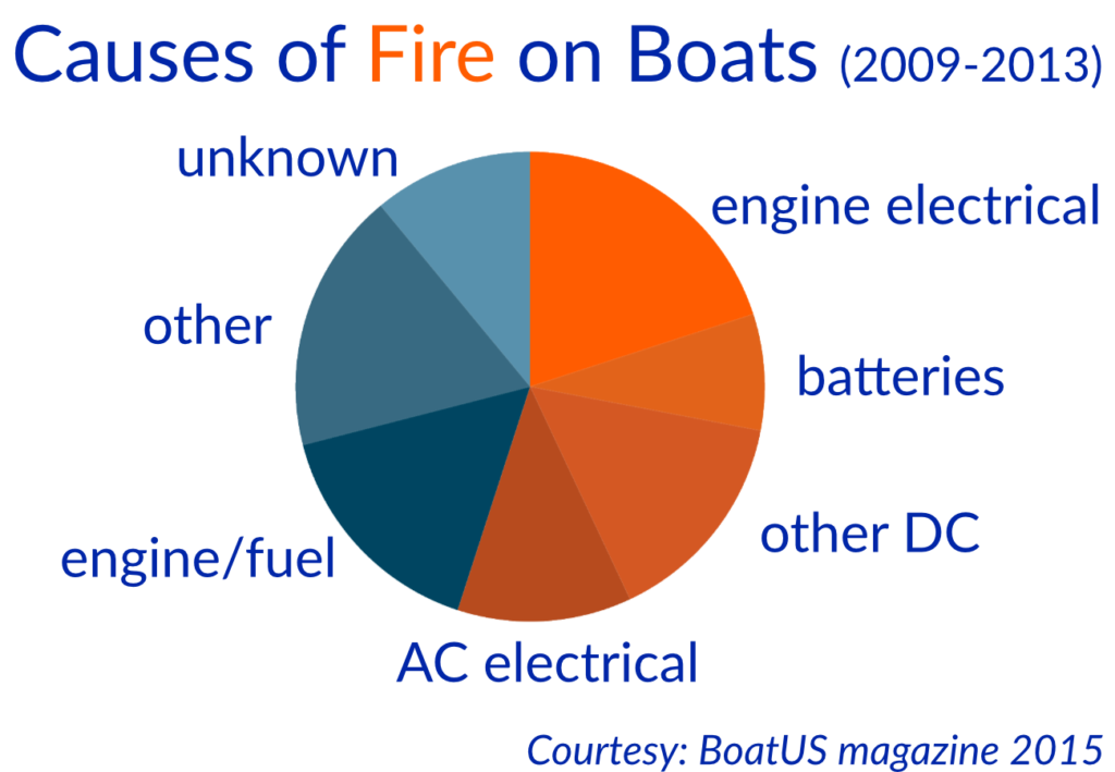
Boat Electrics 101
Boat Electrics 101 is the online course I desperately wish we’d had at the time. It launched in 2021 and was created by arguably the world’s smartest people on marine electrics including boat systems guru, Nigel Calder.
If you’re not familiar with Nigel, you’ll find his mechanical and electric books in just bout every bluewater cruiser’s library. These guys really know what they’re talking about!

In the course you’ll learn:
- The basics of how electricity works
- Electrical system components and how to safely connect them
- How batteries work (and what you can do to double or triple their lifetime)
- Energy system design: how to balance your energy storage, consumption, and generation
- How to plan a (re)wiring of your boat (including making your own boat wiring diagram)
Unlike my grade 10 science teacher, the course does a great job of taking an important concept and breaking it down with animations, diagrams, and videos.
For example, In one module, Calder demonstrates the importance of circuit breakers by driving a screw through an unprotected wire. The cable immediately went up in flames, filling the room with smoke! Lesson learned.
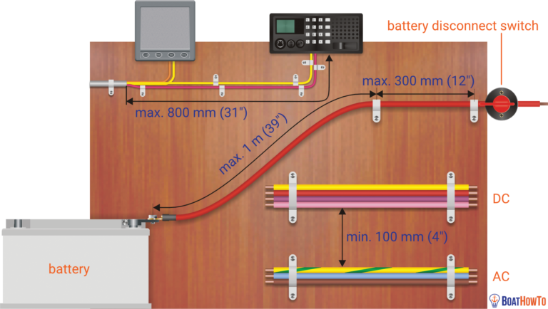
Best of all, all of their materials follow ABYC and ISO standards. Both Nigel and Michael have been members of American Boat and Yacht Council (ABYC) and the International Organization for Standardization (ISO) committees, so they know the rules and best practices better than anyone.
I’ve taken Boat Electrics 101 and can’t say enough good things about it. If you sign up now, you can take advantage of their early bird offer ($199) and save $100 . Oh, and you keep your access to the course forever (even as they add new material). Even if it saves you hiring a marine electrician just once, the course more than pays for itself.
The rewards of doing it yourself
Learning how to wire a boat was not only rewarding but it made us more capable, self-sufficient boat owners. It’s an essential skill for people with older boats, but even new boat owners will find there comes a day when an electrical component fails or they want to add more bells and whistles.
We’ve saved a lot of money by doing our own marine electrical work (not to mention avoided days stuck in port waiting for a professional marine electrician). So, don’t let marine wiring intimidate you. With the right knowledge and tools, you’ll be well on your way to doing your own marine electrical.

Fiona McGlynn is an award-winning boating writer who created Waterborne as a place to learn about living aboard and traveling the world by sailboat. She has written for boating magazines including BoatUS, SAIL, Cruising World, and Good Old Boat. She’s also a contributing editor at Good Old Boat and BoatUS Magazine. In 2017, Fiona and her husband completed a 3-year, 13,000-mile voyage from Vancouver to Mexico to Australia on their 35-foot sailboat.
Sunday 23rd of January 2022
I learned the hard way about boat electrics when locked onto the engine block and a battery charger on a sailboat connected to shore power with a faulty ground. I was being tazered by 240v.
My friend saved my life by pushing me off the engine with a broom handle!
Yes, understanding boat electrics is something that is as important as navigation!
Oh my gosh, that sounds terrifying! What a nightmare. I'm glad you're okay. That was some good quick thinking on your friend's part!
Terms and Conditions - Privacy Policy
- BOAT OF THE YEAR
- Newsletters
- Sailboat Reviews
- Boating Safety
- Sailing Totem
- Charter Resources
- Destinations
- Galley Recipes
- Living Aboard
- Sails and Rigging
- Maintenance
- Best Marine Electronics & Technology
Sailboat Electrical System Upgrades
- By Ed Sherman
- Updated: April 7, 2021

If you’ve been attending boat shows for the past 10 or 20 years like I have, you have surely noticed significant design evolutions from the major sailboat builders. Wide beam carried all the way aft to a plumb transom—which often articulates into a sweet boarding deck, sometimes even opening up a garage for a tender and motor—are becoming the norm. Dual helms and twin rudders are commonplace, and you’d be hard-pressed to find a boat without installed air conditioning and sophisticated refrigeration systems. Boats 30 feet and longer often have a bow thruster as an option, and shore power is standard equipment.
Recently I had the opportunity to turn on the not-so-way-back machine and take a trip to the 1980s to remind me what life on board back then was about. Let me share with you some of my observations and what I would consider changing if I were to buy such a boat.
The sample boat here is a Germán Frers-designed 1983 Beneteau First 42, offered for sale by Dave McKenny at Brewer Yacht Sales in Rhode Island. It is a one-owner boat that was repowered about 10 years ago, and its hull and deck have been repainted. The interior woodwork is the classic dark bright finish of the era and is in excellent condition. More common to that time, the boat has two proper sea berths port and starboard, amidships above and behind the standard saloon settees. And the upholstery has been updated.
The onboard electrical and electronic systems, however, are mostly original, with the exception of a fairly recent autopilot, a 1,000-watt DC-to-AC electrical inverter and an Isotherm seawater-cooled DC refrigeration/freezer upgrade for the original icebox in the galley. The boat has no shore-power system installed, which amazingly was not that uncommon back then. There is no bow thruster or electric windlass; winches are all sized properly but fully manual. So the question is, what would I do to bring this boat’s almost-40-year-old electrical/electronic systems into the new century?

Step one would be to analyze the existing source of electrical power. Currently the boat is equipped with a pair of Group 31 flooded-cell lead-acid batteries. They get recharged by a stock 65-amp alternator controlled by an ancient Balmar voltage regulator. This battery bank has an amp-hour capacity of about 200 amps, but unfortunately flooded lead-acid batteries like these suffer from cycle-life reduction if they get continually discharged below about 50 percent of their capacity. In effect, this boat currently has about 100 amp-hours of power available for running accessories.
In my dream redo, this would not be adequate, and I consider it marginal even as the boat is equipped now without a bit of engine run time to keep those batteries charged.
For me, one of the first upgrades would be to replace these batteries with a pair of group 31 absorbed glass-mat batteries. AGMs have considerably higher recharge-acceptance rates compared with flooded-cell batteries, and can be discharged up to 80 percent of capacity, meaning that engine run times will be at a more acceptable level when away from the dock, at least in terms of electrical-power generation. Upgrading the alternator and voltage regulator to a 100-amp Balmar set would also be on my list for this boat to minimize engine run time.
My intention is to add quite a bit more electrical equipment to this boat, and I prefer not to run things such as alternators near their maximum capacity for extended periods of time. Limiting the amount of full output extends their potential service life considerably.

Plug and Play
AC power on board today is almost a must for boats that are going to be berthed at a dock. Yes, global warming is real, and sleeping on board without air conditioning at this point in my life just isn’t happening.
I’ve lost my enthusiasm for cold showers as well. In the old days, we used sun showers hanging from the boom in the cockpit and got by just fine, but that was then and this is now. The luxury of hot water on demand is not too much to ask in this day and age. So besides adding air conditioning to this boat, we are going to need to add a water heater and appropriate plumbing to deliver hot water to the galley and two heads.
The current refrigeration system, an Isotherm ASU unit, is only a 12-volt, and I would think about swapping that out for a 12-volt DC/120-volt AC unit. Or, as a money saving measure, I might just leave the 12-volt unit in place because I’m going to be installing a proper battery charger to keep my new AGM batteries charged up anyhow. We’ll let the charger replenish the power used by the Isotherm unit.
The bottom line here is that the boat is going to get shore power installed for the first time. The question becomes whether a 30-amp system or a 50-amp system will be needed. Determining that requires performing a load analysis. Here’s how I would go about doing it.
First we have to determine how many Btu we’re going to need to cool the boat. A visit to marinaire.com will connect you with a calculator that will provide the Btu per hour needed to air-condition the boat in either moderate or tropical environments. I chose moderate for this boat because based on MarineAire’s world map, only South Florida is in its tropical zone, and the plan for this boat is to stay in the mid-Atlantic to Northern states the majority of the time.
Based on the calculator results, I still came out needing one of the company’s largest units, which can produce 16,000 Btu of AC and 17,000 Btu of heat when needed. This unit draws just under 11 amps of AC power at 110 volts.
My new water heater will draw 13 amps, and I’ll need another 8 amps for my P-12 Blue Sea 40-amp battery charger.

With an air conditioner, water heater and battery charger plugged in and running, we’re looking at just over 30 amps of AC power needed. That figure does not include any provision for a microwave oven, coffee maker, hair dryer or any other small AC appliance while at the dock.
Knowing this opens up two options for shore power: either a 50-amp service or possibly two 30-amp setups. The potential problem here is the marina itself; many don’t offer a 50-amp option at the dockside pedestal. There are myriad adapters available that would allow you to tap into multiple outlets to get to 50 amps, but remember: You don’t want to pull more than 30 amps from a 30-amp service.
One additional shore-power consideration on this boat is the 1,000-watt DC-to-AC inverter that has been installed. This was possibly done to facilitate running a laptop at some point, or maybe an electric shaver or small hair dryer. It is located in the aft head compartment, so I’m going with the shaver idea.
My inclination would be to relocate the inverter behind a panel in the navigation-station area, probably under the settee at the nav station, and resize it to a 2,000-watt unit. I would add a dedicated battery to supply DC power to the inverter and make sure the battery is connected to my Blue Sea charger. Since I am going to be running only intermittent loads from the inverter, a group 27 AGM will get the job done.
Note that I am not considering a generator for this major upgrade. Space is tight, and I don’t want to carry the extra weight. This is a performance cruiser, and I want it to stay that way. Besides, my plan is to stay mostly in slips when traveling, and so I’ll have access to shore power when I need it.
A Wednesday-night race series is in the plan as well, so I won’t be adding a bow thruster, anchor windlass or electric winches. For the occasional overnight away from the dock, I will still have the power I need to microwave some popcorn and run a laptop to check a weather forecast or watch a downloaded Netflix movie.
Side note: I have no plans to add solar panels or a wind generator either. I love the lines of this boat just the way Frers designed it.

Based on the proposed changes to the electrical system, a new AC/DC combined panel is in order. The boat is currently equipped with 12 DC circuits and no AC circuits. We will also need to modify the battery-switching system, so that will allow the three new batteries, combined, to be separated.
For the panels, Blue Sea, Paneltronics and Bass Products are all possibilities. I just need to take some measurements to see what will fit where the existing panel is mounted. The design will also depend on whether I decide to go with a single 50-amp shore-power service or two 30-amp services.
In either case, rather than having two cigar-lighter-style outlets, we’ll swap those out for a pair of Blue Sea USB plug adapters, which are more relevant in today’s world.
Instruments and Toys
With the exception of the autopilot, the original onboard electronics need to be replaced. A pair of multifunction displays are in order here, with one mounted at the traditional nav station down below and another in a pod at the helm. An updated VHF with digital selective calling and possibly integrated AIS will also be needed. And since trips north to Maine from Annapolis will be part of the plan, we’ll add radar. Air, wind and speed instruments will also be integrated via NMEA 2000. Since coastal cruising is going to be the primary use for this boat, satellite communications will not be part of the permanent upgrades.
I’m not a television person, so a boat with a flat-screen TV that rises up from behind a settee and interfaces with the chart plotter means nothing more to me than just one more thing that can break and need repair. I do have an iPad loaded with my favorite tunes though, so some speakers and a small AM/FM stereo set that connects to my iPhone or iPad via Bluetooth will augment the good company I plan to have on board for entertainment.

Dollars and Sense
The used-boat market has a huge inventory these days, and there a lot of really great boats available for any price range—and at considerable savings compared with the cost of a new boat.
This Beneteau First 42 that I have my eye on has an asking price of $59,900. Although there is no direct comparison for the 2020 model year from Beneteau, a similar boat in this size range would cost over $200,000. That’s at least a $140,000 differential.
That can buy a lot of upgrades!
The proposals I suggest here will not be inexpensive, but when compared with the cost of a new boat with similar equipment (much of it optional), you can come out tens of thousands of dollars ahead with careful selection of the right used boat. I think the biggest part of any decision here is to be totally honest with yourself about your genuine needs versus your dreams and desires.
Ed Sherman writes frequently on a range of technical topics for CW. He is a longtime Boat of the Year judge, and recently retired as vice president of the American Boat & Yacht Council.
- More: electrical systems , Electronics , Hands-On Sailor , How To , print 2021 mar
- More How To

3 Clutch Sails For Peak Performance

It’s Time to Rethink Your Ditch Kit

8 Ways to Prevent Seasickness

How To De-Winterize Your Diesel Engine

Kirsten Neuschäfer Receives CCA Blue Water Medal

2024 Regata del Sol al Sol Registration Closing Soon

US Sailing Honors Bob Johnstone

Bitter End Expands Watersports Program
- Digital Edition
- Customer Service
- Privacy Policy
- Email Newsletters
- Cruising World
- Sailing World
- Salt Water Sportsman
- Sport Fishing
- Wakeboarding
- Forums New posts Unanswered threads Register Top Posts Email
- What's new New posts New Posts (legacy) Latest activity New media
- Media New media New comments
- Boat Info Downloads Weekly Quiz Topic FAQ 10000boatnames.com
- Classifieds Sell Your Boat Used Gear for Sale
- Parts General Marine Parts Hunter Beneteau Catalina MacGregor Oday
- Help Terms of Use Monday Mail Subscribe Monday Mail Unsubscribe
Best Schematic Drawing Tool for Boat Electrical Systems?
- Thread starter jviss
- Start date Feb 16, 2022
- Forums for All Owners
- Ask All Sailors

Hi all, What do you all think is the best tool for drawing boat schematics? Something free or cheap, maybe? Thanks, jv

Graph paper, mechanical pencil, and template. Don't have to boot it up, inexpensive, easily modified, no updates, no printer ink required.

Head Sail said: Graph paper, mechanical pencil, and template. Don't have to boot it up, inexpensive, easily modified, no updates, no printer ink required. Click to expand

There is a "language" to drawing wiring diagram. To draw such that the reader understands the diagram requires electrical engineering training. There are templates you can buy to draw devices such as relays, terminal blocks, etc. All you need is a straigh edge and pencil.

DayDreamer41
Electrical or Mechanical?, I have done both on excel, you just have to be creative with the symbols. There are a few low cost software packages out there thought Edraw Max I guess appears to be a fairly decent package but like with any package there is a learning curve, where a pencil and 1/4 line pad has immediate results.
Just to clarify the queston. I am an electrical engineer, and I've done some mechanical design too, and have used professional schematic capture and solid modeling software. I want a software, computer-based solution. I want that so I can find and save things on my Mac, and so I can create lots of version, extract parts lists and net lists, do design rules checking, maybe even run simulations. Thanks, jv
jviss said: Just to clarify the queston. I am an electrical engineer, and I've done some mechanical design too, and have used professional schematic capture and solid modeling software. I want a software, computer-based solution. I want that so I can find and save things on my Mac, and so I can create lots of version, extract parts lists and net lists, do design rules checking, maybe even run simulations. Thanks, jv Click to expand
Electrical Design Software - Electrical CAD Toolset | Free Online App
Schematics diagram software for linux - edraw.
DayDreamer41 said: I have trouble believing that you can find something to do all that which is either free nor cheap..... Click to expand

When you find it, let us know.
PCB CAD Software – ExpressPCB

Attachments
- Boat wiring.pdf 12.7 KB Views: 615
lucidchart is a flowchart/diagram tool that has circuit diagrams.

garymalmgren
DayDreamer41 said: Electrical or Mechanical?, I have done both on excel, you just have to be creative with the symbols. There are a few low cost software packages out there thought Edraw Max I guess appears to be a fairly decent package but like with any package there is a learning curve, where a pencil and 1/4 line pad has immediate results. Click to expand
We use Visio at work but it isn't free. The Open Office Suite is a great package and your tax dollars paid for it.
Maine Sail said: +1For eDraw Max Click to expand
- This site uses cookies to help personalise content, tailor your experience and to keep you logged in if you register. By continuing to use this site, you are consenting to our use of cookies. Accept Learn more…
Service Locator
- Angler Endorsement
- Boat Towing Coverage
- Mechanical Breakdown
- Insurance Requirements in Mexico
- Agreed Hull Value
- Actual Cash Value
- Liability Only
- Insurance Payment Options
- Claims Information
- Towing Service Agreement
- Membership Plans
- Boat Show Tickets
- BoatUS Boats For Sale
- Membership Payment Options
- Consumer Affairs
- Boat Documentation Requirements
- Installation Instructions
- Shipping & Handling Information
- Contact Boat Lettering
- End User Agreement
- Frequently Asked Questions
- Vessel Documentation
- BoatUS Foundation
- Government Affairs
- Powercruisers
- Buying & Selling Advice
- Maintenance
- Tow Vehicles
- Make & Create
- Makeovers & Refitting
- Accessories
- Electronics
- Skills, Tips, Tools
- Spring Preparation
- Winterization
- Boaters’ Rights
- Environment & Clean Water
- Boat Safety
- Navigational Hazards
- Personal Safety
- Batteries & Onboard Power
- Motors, Engines, Propulsion
- Best Day on the Water
- Books & Movies
- Communication & Etiquette
- Contests & Sweepstakes
- Colleges & Tech Schools
- Food, Drink, Entertainment
- New To Boating
- Travel & Destinations
- Watersports
- Anchors & Anchoring
- Boat Handling
12 Volt Electrical Systems
Advertisement

Battery Switches
The majority of boats on the water today depend on electricity to some degree. Unfortunately, too many of those boats are operating with inadequate and poorly installed electrical systems. This can result in unnecessary problems that drain your patience and pocketbook and that can cause safety issues. A quick fix may alleviate the problem for the short term, but if the system remains inadequate, problems will continue to plague it.
To begin taking the right steps to achieve a good electrical system on your boat you need to:
- Determine your power requirements
- Provide adequate power storage and starting capacity
- Provide the proper charging that you need
- Be sure your wiring is adequate and approved for marine use and connections are sound
- Engage a qualified professional if needed
- Be sure that all safety requirements, such as the relevant ABYC standards, are met
Your boat's batteries are a cornerstone of a good electrical system. Power boats that are used simply to run from dock to dock on weekends may need only one (always two are preferable) starting battery which we'll discuss below. These are less expensive and lighter than batteries designed for deep cycling, which is what you'll need if you stop for periods of time to anchor or drift or, far more importantly, if you plan to anchor overnight. Boats that are used for long term anchoring, as in serious cruising, need batteries capable of deeper discharges and of greater storage capacity. Such batteries include wetted lead acid, gel and AGM deep cycle types. However, even if you just plan to run from dock to dock or dock to fishing ground or beach and back, it's important to realize that you may be using electricity during those times that the engine is off and be prepared with the right type and size of batteries.
Batteries need good wiring to deliver the power supply to the gear onboard. That's the subject of " Wiring ". Since batteries are essentially fuel cells, charging the batteries is another important element. For additional detail on that subject go to our Battery Chargers article . There are both DC (direct current as from 12 volt batteries) and AC (alternating current like what you use in your house) systems and issues on many boats, although some boats, particularly smaller ones, only use DC. Here we'll discuss primarily DC. AC options are discussed in some detail in the section " Inverters ".
Determining Your 12-Volt Power Requirements
First, calculate your daily (24-hour) average power consumption for all of the electrical loads you place on your system. List all of the appliances and their amp draws. If amps are not listed on the appliance, you can figure amps with the following formula:
amps = watts / volts
Next, estimate the normal daily usage for each in hours, so that you have a list of appliances and their daily draw in amp-hours (Ah). Now total them all up. But don't cut it close. As battery voltage lowers with us amperage draw will go up. Also, amperage draw increases with wire run. This means that the total of the power consumption numbers on your equipment will probably be less than your actual usage. For further information see the article on Inverters .
What Size Battery Do You Need?
Let's assume your daily power consumption totals 100 Ah. A 100-Ah battery won't do it. Why? Because battery capacity is determined in part by the intervals between battery charges, and the discharge level. A 100-Ah battery might in theory meet your daily energy requirements, but would have no reserve. And a battery should never be fully discharged. It must be able to store and deliver the full 100-Ah between charges. Further, with each partial discharge of your battery its capacity will gradually diminish.
Automotive starting batteries are made for starting engines, with the quick release of a big burst of power. They discharge only about five percent, and are intended to be immediately recharged by the alternator. They cannot handle the repeated deep discharges typical of marine use and they may suffer damage from the constant pounding they receive at sea. Conventional wet (lead acid) deep cycle batteries or deep-cycle gel cells or AGM batteries are best at withstanding the deep discharges, rapid high power recharging, and the physical pounding of the marine environment. Look for batteries with the greatest number of life cycles at 50% discharge and do not mix batteries of different construction type (such as, for example, wetted lead acid and AGM) in the same bank - use one or the other. There are also dual purpose batteries claimed to provide relatively high engine starting power for their size but also relatively good deep cycling capability. (Don't count on these for cruising with repeated heavy deep cycling.)
You will possibly double the life of your battery if you don't discharge it below 50% capacity. Consider also, for example, that lead acid batteries recharge rapidly only up to around 70-80% of capacity. If you don't want to spend a lot of time recharging that last 30%, plan on using only about 30% of the battery's full capacity. And it's better to consume even less than that because no battery operates at 100% over its full life. Also, give yourself a little power in reserve. Given all this you, in theory, will need a 400-Ah wetted lead acid battery to meet your 100-Ah daily energy habit. In general, a battery rated at four times your daily usage will be adequate. But, as noted, this is only theoretical. Other factors, such as, for example, voltage drop (and therefore amperage increase) caused by long wiring runs, will affect the usage and size requirements. For further information see the article entitled "Inverters" . If you're thinking that all this sounds like a real drag; that you're going to need to be boating with a calculator to deal with batteries, relax. With good modern battery chargers and alternators and a little common sense and observation on your part, your equipment will handle much of these issues. There's more on this below.
Battery Banks
Reserve an adequately-sized, fully charged battery or bank of batteries solely dedicated to starting your engine. Some prefer to use what are commonly referred to as "starting batteries" dedicated to engine starting. These typically have thinner plates but more plates and therefore can deliver more Cold Cranking Amps (CCA) for size and weight. CCA is the measure of how many amps the battery will supply to the starter motor for 30 seconds continuous at 0°F while maintaining its voltage above 7.2 volts. Marine batteries may also be rated in Marine Cranking Amps (MCA) which is similar to CCA except at 32 degrees F. Starting batteries are typically not as tough in construction as batteries designed for deep-cycling and less expensive. These will not serve well if you need them for deep-cycling because such will quickly deplete them, leading to early failure. A deep-cycle battery can be used for engine starting, as long as it provides enough cold-cranking amps (CCA) to easily start your engine.
Use a separate bank of deep-cycle "house" batteries to supply the rest of the boat's electrical needs. Or, you can use two banks of deep-cycle batteries, each with enough cold-cranking amps to start the engine. Parallel the two banks with a dual-purpose battery isolation/selector switch for tough engine starts and then alternate between the two banks for "house" use. Always, however, keep one bank fully charged for starting.
Battery Charging
If you don't replace what you use, your batteries will eventually go dead, no matter how much battery capacity you have on your boat.
The rate at which you can recharge your batteries depends on a number of factors including how much you discharged them, the condition of the battery, the temperature, the alternator's power (in amps) and its output (in volts) as well as an AC battery charger's capacity and features.
Many boats charge their batteries with an engine-driven alternator. If your engine running time is minimal, you want to charge as quickly as possible, without damaging the battery. Battery damage begins when the internal temperature becomes too high, causing it to gas and heat up. If it feels warm to the touch or if you're smelling gas, it's getting too hot. A smart voltage regulator for the alternator should control and taper off the charge to prevent this and can also be set, within limitations, to accommodate your needs. More on this below.
The marine alternator is generally more suitable for use on a boat than the typical automotive alternator sometimes found as original equipment on new gas and diesel engines. Alternators are typically rated in amps; the rating refers to the maximum output in one hour at a certain temperature and rotation speed. Typical automotive alternators can't run continuously at full load in the warm temperatures found around boat engines, or in warm climates. Further they have internal voltage regulators that are set to deliver a rapid charge to a starting battery, not to deliver sustained tapered intelligent deep cycle recharge for house batteries. A suitable marine alternator may be rated at full continuous load at temperatures up to 200°F. Some marine alternators have special grease in the bearings and other special construction to withstand the higher running temperatures and loads as they continue to put out at higher levels during deep cycle recharging. They are also more robust in many other respects.
A good rule of thumb is that you will need at least 120% of the energy you used to restore the battery. And to prolong the life of your alternator, plan on running it at less than full output. Take into account any other power-draining loads you might be adding to the system as you are recharging, such as refrigeration or inverters. If you install an oversized alternator, you can recharge efficiently while at anchor, with the engine at idle and the alternator operating below its rated speed and output. (However, it isn't helpful to the engine to run it for long periods of time under low load. Many prefer to charge batteries while at anchor using an AC generator and AC battery charger. More on this below.) Again, a "smart" regulator which you can set to perform optimally for your parameters is needed.
The speed of your alternator's rotation is a function of engine RPMs and your alternator's pulley wheel size. Once you have determined the maximum alternator output you require, add around 25% or more so you won't have to operate it at full bore to achieve the required results. Now check how many alternator RPMs it takes to reach that output. Then determine the minimum engine RPMs at the engine's power take off wheel at which you will be charging. You need a pulley ratio that gives you maximum required output at your minimum engine speed. If you need 110 amps, and it takes an alternator RPM of 4,000 to generate it, and your engine is running at 1,000 RPMs, then you need a 4:1 pulley. Make sure that if you punch your engine up to 3,000 RPMs, thereby increasing your alternator speed to 12,000, you are not exceeding maximum safe alternator speed. Typically, the manufacturer of a good marine alternator should provide this information for your application and also the alternator pulley wheel that you need.
Voltage Regulation
A voltage regulator determines the rate and manner which an alternator or AC charger will charge your battery. Normally we think of voltage regulators specifically for alternators, but even AC chargers have internal components that determine rate and manner of charge. In better units these internal components can be field adjusted. If charging isn't done properly your batteries can suffer failures ranging to total depletion to overheating, gassing and essentially self destructing.
The basic alternator voltage regulator maintains voltage at a certain level by matching alternator output with the load and the charge level of the battery. Voltage drops when a load is placed on the power system, or when the battery discharges. The regulator then increases the amperage output of the alternator until the voltage level is restored, and then tapers output to a level that will sustain that voltage.
You should have a regulator that is external, and field adjustable, so that you can adjust the alternator's performance, tailoring the alternator's output to the type and size of battery(s) that you are charging. A "smart" voltage regulator can also be set to charge specific types of batteries in a way that will not only charge them well, but also give them longer life. A good marine adjustable smart voltage regulator should be able to charge at three stages, often called "bulk, absorption and float." Bulk puts a lot of power into the battery rather fast, to bring it up rapidly to a certain point. Then the regulator will switch to absorption mode before the battery gets too hot or gasses or becomes otherwise damaged. At absorption, charging occurs more slowly to provide more subdued charge commiserate with the state of charge of the battery. Once the voltage is at the desired level the regulator shifts into float which essentially maintains the battery, making adjustment for usage. Some regulators even have heat sensors on the bank(s) so that they can compensate for that factor. Of course all of this must be set for the parameters of your battery and/or bank. Different sizes and different types (such as lead acid, Gel and AGM) of batteries require different types and rates of charging, as well as different voltage levels. Usually instructions with the voltage regulator will help you with this.
Your 12 volt system can also be used to supply AC current, like you have in your house, with the addition of a marine approved inverter which will invert the DC current (normally obtained from your battery bank) to AC. For further information see our article on Inverters.
Inverters increase the load on the battery and bank size and alternator charging must compensate for this. Of course, the greater the AC draw from the inverter, the greater the inverter's DC draw from the battery. Also, as the inverter is converting at higher amps, its efficiency will diminish, again causing higher rate of battery depletion. This makes it even more important to have a robust marine alternator controlled by an external adjustable voltage regulator. With suitable equipment, you can use AC current while you are running and keep the batteries topped up. If the battery banks are large enough for your consumption and properly charged, you can have quiet times at anchor with AC power available without running the generator all the time.
There are now AC powered battery chargers on the market that can charge and maintain not only different banks but also banks that have different construction techniques, such as wetted lead acid, gel and AGM. These essentially jump from bank to bank in sensing and do what's needed for that bank. Of course, you must set these up appropriately for your system. When you charge your batteries when AC is available (from the dock or from an onboard marine generator) through a battery charger, it should be rated for marine use and also have "smart" charging with similar charge settings and charge characteristics discussed above as to the alternator's voltage regulator.
With multiple battery banks many people prefer to have a device which automatically shifts charging output to different banks so that no one bank is overcharged. However many prefer to monitor bank status manually and use a battery selector switch to direct charging current to the appropriate bank. Failure of automatic devices, often hidden away in an engine space, can result in improper charging leading to discharge or overcharge which will "cook" a battery, ruining it, and which could cause explosion or emission of large amounts of corrosive explosive gas.
Wind and Solar Charging
Many people also use wind generators and solar cells to keep their 12 volt system charged. Solar cells generally have less output for the money than wind generators and require special mounting racks or cabin or bimini top space. Wind generators can usually put out more current, but only if the wind is up. They make noise, which some find objectionable but others find soothing. Usually people become accustomed to it. Great care must be taken to avoid being hit by a propeller and also to shut it down when the wind gets too high. Better wind generators have a self contained automatic dampening mechanism to prevent over-speed in high winds. One or both systems are often used by those who don't consume much electricity or who want to keep their batteries up while they're off the boat, particularly as when there's no dock power available as when they're at anchor or on a mooring. Even with these systems you must provide overcharge protection. Devices that do this usually come with the wind generator or solar cell.
We can only scratch the surface of this subject, which could easily fill a large book. If you want to be hands on (and that's good) read some of the many books on the subject. In any event, it never hurts to involve a well trained competent professional when dealing with any kind of electricity on a boat.
Technology, knowledge and practices change almost daily therefore it is prudent to research for the very latest up to the date information and seek qualified professional assistance when needed.
Related Articles
The truth about ceramic coatings for boats.
Our editor investigates the marketing claims of consumer-grade ceramic coatings.
Fine-Tune Your Side Scan Fishfinder
Take your side-scanning fishfinder off auto mode, and you’ll be spotting your prey from afar in no time
DIY Boat Foam Decking
Closed-cell foam flooring helps make boating more comfortable. Here’s how to install it on your vessel
Click to explore related articles
BoatUS Editors
Contributor, BoatUS Magazine
Award-winning BoatUS Magazine is the official publication of Boat Owners Association of The United States. The magazine provides boating skills, DIY maintenance, safety, news and more from top experts.
BoatUS Magazine Is A Benefit Of BoatUS Membership
Membership Benefits Include:
Subscription to the print version of BoatUS Magazine
4% back on purchases from West Marine stores or online at WestMarine.com
Discounts on fuel, transient slips, repairs and more at over 1,200 businesses
Deals on cruises, charters, car rentals, hotel stays and more…
All for only $25/year!
We use cookies to enhance your visit to our website and to improve your experience. By continuing to use our website, you’re agreeing to our cookie policy.
- Consultation & Design
- Installation & Service
- Boating Tech Talk
- Case Studies
- Testimonials
- PYS Merchandise
- PYS Donation
- 9'> Diagrams
Conceptual Diagrams
PYS is providing these conceptual diagrams to demonstrate a typical installation. For simplicity, the diagrams primarily show the DC positive or AC hot side of the circuit.
Remember these conceptual diagrams should not be relied on for installation purposes, start with a solid plan by engaging PYS remotely for technical advice and tailored marine electrical plans for your boat.

Diagrams AC & DC Generator

Diagrams AC Overview

Diagrams AC Panel

Diagrams Battery Charger

Diagrams Battery Combiner

Diagrams Battery Isolator

Diagrams Battery Monitor

Diagrams DC Overview

Diagrams External Regulator

Diagrams Galvanic Isolator

Diagrams Inverter

Diagrams Methanol Fuel Cell

Diagrams Networking

Diagrams Solar Panels
Looking for a sounding board, start with a solid plan by engaging pys remotely for technical advice and tailored marine electrical plans.

Schedule Consultation
Consultation & Design Process

Copyright © 2024 Pacific Yacht Systems.
Contact Us 604.284.5171
PYS Partners | Privacy Policy

Marine Electrical Diagram
Quick Links
- Key Features
- Video Tutorials
Electrical Single-Line Diagram & Views
Create, configure, customize, and manage your marine electrical system model. Core modeling and tools allow you to quickly and easily build 3-phase, 2-phase, 1-phase, AC / DC network one-line diagrams with unlimited buses and elements including detailed marine cables, DC Link and protection equipment.

- Fully integrated view with multiple voltage level handling
- Unlimited main panel / distribution boards and graphical sub-panels
- Integrated 3-phase, 2-phase, 1-phase
- Integrated AC, DC, grounding & earthing systems
- Multi-level nesting of sub-systems
- Interfaces for management of switching devices
- Charger / Rectifier / UPS modeling
Auto-Build is an automated and powerful tool for creating and editing the one-line diagram. The rule-based design of Auto-Build can significantly reduce the time spent on creating a one-line diagram.
- Automated creation of a one-line diagram without leaving the equipment toolbar
- Quick & intuitive one-line diagram generation
- Automatic spacing & alignment rules
- No need to drag, drop, locate, and connect
- Customize input data & study results
- Display results, tags, and/or properties
- Define templates & share
- Automatically apply templates
- Instant preview of Datablock

Composite Network & Motors
Composite Networks or nested networks allows users to model a portion of their project and represent it as a single element, providing a more simple and organized appearance. Composite networks can be nested for an unlimited number of sub-networks, allowing for multiple layers in one project.
- Customizable Views
- Unlimited Connections
- User-Defined Location & Sizing
- Visualize Properties & Results
Theme Manager
Set different themes for individual one-line diagrams. Themes can be color coded based on standard, voltage level, area, system grounding, earthing, deenergized elements, feeder, etc. Color contouring or user-configurable 'heatmaps' may also be applied behind the one-line diagram. One-line diagram color based contouring is based on voltage or power flow magnitude. ETAP allows for one-line diagram decluttering based on:
- Equipment type
- Equipment state
- Info annotations
- Study results
White Papers
Electrical Power System Analysis & Operation Software
- Help Center
- Global Support
- User Testimonials
- System Requirements
- Partner Program
- Technology Partners
- Solution Providers
- Educational Partners
- Product Overview
- Sample V&V Cases
- Specifications for Studies
Subscribe to ETAP News
Afghanistan Aland Islands Albania Algeria American Samoa Andorra Angola Anguilla Antarctica Antigua and Barbuda Argentina Armenia Aruba Ascension Island Australia Austria Azerbaijan Bahamas Bahrain Bangladesh Barbados Barbuda Belarus Belgium Belize Benin Bermuda Bhutan Bolivia Bosnia and Herzegovina Botswana Bouvet Island Brazil British Indian Ocean Territory Brunei Darussalam Bulgaria Burkina Faso Burundi Cambodia Cameroon Canada Cape Verde Cayman Islands Central African Republic Chad Chile China Christmas Island Cocos-Keeling Islands Colombia Comoros Congo - Brazzaville Congo - Kinshasa Cook Islands Costa Rica Cote d'Ivoire Croatia Cuba Cyprus Czech Republic Democratic Republic of the Congo Denmark Djibouti Dominica Dominican Republic Ecuador Egypt El Salvador Equatorial Guinea Eritrea Estonia Ethiopia Falkland Islands Faroe Islands Fiji Islands Finland France French Guiana French Polynesia French Southern Territories Gabon Gambia Georgia Germany Ghana Gibraltar Greece Greenland Grenada Guadeloupe Guam Guatemala Guernsey Guinea Guinea-bissau Guyana Haiti Heard Island and McDonald Islands Honduras Hong Kong Hungary Iceland India Indonesia Iran Iraq Ireland Isle of Man Israel Italy Jamaica Japan Jersey Jordan Kazakhstan Kenya Kiribati Korea, North Korea, South Kosovo Kuwait Kyrgyzstan Laos Latvia Lebanon Lesotho Liberia Libya Liechtenstein Lithuania Luxembourg Macau Macedonia Madagascar Malawi Malaysia Maldives Mali Malta Marshall Islands Martinique Mauritania Mauritius Mayotte Mexico Micronesia Moldova Monaco Mongolia Montenegro Montserrat Morocco Mozambique Myanmar Namibia Nauru Nepal Netherlands Netherlands Antilles Nevis New Caledonia New Zealand Nicaragua Niger Nigeria Niue Norfolk Island Northern Mariana Islands Norway Oman Pakistan Palau Palestinian Panama Papua New Guinea Paraguay Peru Philippines Pitcairn Poland Portugal Puerto Rico Qatar Reunion Island Romania Russia Rwanda Saint Barthelemy Saint Helena Saint Lucia Saint Martin Saint Pierre and Miquelon Samoa San Marino Sao Tome and Principe Saudi Arabia Senegal Serbia Seychelles Sierra Leone Singapore Slovak Republic Slovenia Solomon Islands Somalia South Africa Spain Sri Lanka St. Vincent & The Grenadines Sudan North Sudan South Suriname Svalbard and Jan Mayen Swaziland Sweden Switzerland Syria Taiwan Tajikistan Tanzania Thailand Timor-leste Togo Tokelau Tonga Trinidad and Tobago Tunisia Turkey Turkmenistan Turks and Caicos Islands Tuvalu Uganda Ukraine United Arab Emirates United Kingdom United States United States Minor Outlying Islands Uruguay Uzbekistan Vanuatu Vatican City Venezuela Vietnam Virgin Islands Wake Island Wallis and Futuna Western Sahara Yemen Zaire Zambia Zimbabwe
- Legal Notices
- Privacy Policy
© 2024 Operation Technology, Inc. All rights reserved.
- Catalina Manuals
- Owner's manual
Catalina 36 Owner's Manual
- page of 64 Go / 64
Table of Contents
- Troubleshooting
- Rigging and Hardware
- Operating Check List
- Final Check
- Maintenance Guide
- Pre-Use Maintenance
- Monthly Maintenance
- Seasonal Maintenance
- Fiberglass Maintenance and Repair
- Fiberglass Touch up and Repair
- Teak Maintenance
- Spar and Rigging Maintenance
- Sail Maintenance
- Interior Cushion Fabric Cover Cleaning
- Stepping the Mast
- Rigging Wire Check List
- Internal Halyard Mast Head Assembly
- Main Sail Reefing
- Topping Lift Assembly
- Goose Neck Arrangement
- Deck Hardware Arrangement
- D.C. System Wiring Diagram
- Main Battery Switch
- Main Battery Switch Schematic
- 110 Volt System
- 110 Volt Shore Power Schematic
- 12 Volt Schematic
- Hot and Cold Pressure System Plumbing Schematic
- Manual Bilge Pump
- Through Hull Locations
- Marine Toilet Operations
- Macerator Pump and Troubleshooting
- Holding Tank and Macerator Illustration
- Auxillary Power
- General Engine Information
- Packing Gland Assembly
- Shaft Packing Gland (Stuffing Box)
- Shaft Alignment
- Shaft Alignment Illustration
- Fuel Sanitation
- Exhaust System Maintenance
- Emergency Tiller
- Galley Stove
- CABIN Arrangemnt
- Decommi's's I'oning
- Winterizing Your Engine
- Owner-User 'Responsibility
- General Safety Tips
- Required Safety Equipment
- Suggested Safety Equipment
- Safety Package. Factory Option
- Anchors. Anchoring and Mooring
- Lighting Precautions
Advertisement
Quick Links
- 1 Rigging and Hardware
- Download this manual
Related Manuals for Catalina 36
Related products for catalina 36.
- Catalina 34 MK II
- Catalina 350
- Catalina 310
- Catalina 22 1977
- Catalina 250
- Catalina C-22 1977
- Catalina Capri 22
- Catalina Expo 12.5
- Catalina Expo 14.2
- Catalina Jenny Lane
Rename the bookmark
Delete bookmark, delete from my manuals, upload manual.
IMAGES
VIDEO
COMMENTS
Even a small boat (3-5 loads) we'd recommend at least 12AWG wire for this. 10AWG for larger boats (5-10 loads) is normal. 8AWG is getting toward over-kill in most cases for boats under 30ft. Remember these are all generalities, there are many valid reasons to make exceptions.
Complete guide to wiring a boat electrical system from scratch. Starting from the 12V boat battery, we look at configuring a complete electrical system incl...
The DC electrical system is grounded through the negative bus of the distribution panel, which in turn is grounded through the engine negative terminal or its bus. ... Example Of A Draft Wiring Diagram For A Simple Boat. When you make your own wiring diagram use very large sheets of paper for clarity. Most boats will have positive and negative ...
Wiring Diagrams 19-21 Glossary of Terms 22-23 FAQs (Frequently Asked Questions) 24. 4 understandinG your Boat's electrical systeM Getting to the Heart of the Matter Your boat's AC electric system is a lot like your body's circulatory system. Your heart pumps blood throughout your body via a network of arteries. These arter-
Step 2. Draw a simple electrical schematic (diagram) that shows each piece of equipment, the fuses, switches, and how all of this will be connected. This is not a diagram of where the equipment is located on the boat. That will come in Step 8. It is simply a diagram of the electrical circuits.
The Boat Electrics 101 course is a fantastic resource for beginners like myself who know little about electricity and even less about boats electrical systems. Clearly expressed and illustrated, the course is full of practical information presented in a way that makes boat electrical systems understandable.
Although a fiberglass sailboat can seemingly have a half-life of 50 years or more, its electrical system most certainly does not. Up until the 1990s, few production builders used tinned wiring in their installations, and most owners had fairly basic requirements, allowing boatbuilders to get away with providing rudimentary electrical systems.
Draw a square, label it with the name of the device (inverter, switch) and show the wires that are connected to it. For DC wiring, positive wires are red, negative wires are yellow (or black in some cases). Your boat wiring system should have a marine grade main battery disconnect switch which allows you to open the switch to turn everything ...
Before starting the wiring process, it is crucial to have a wiring diagram and a plan. A wiring diagram is a visual representation of the boat's electrical system and helps you identify the wires and their functions. A plan will help you organize the wiring, identify the locations of switches, panels, and other components, as well as ensure ...
Our review of Boat Electrics 101, a new online course, co-developed by marine electrics expert, Nigel Calder. When we bought our 1970s-era sailboat, the boat wiring was a disaster. We soon discovered a rainbow spaghetti mess of unlabeled electrical wires behind our DC electrical panel. Legacy marine electrical systems from a previous ...
Join Jeff Cote, from PYS, as he goes through the building blocks of a marine electrical system. Jeff will share the lessons learned from designing and insta...
Sailboat Electrical System Upgrades. An electrical expert takes a classic-plastic gem and imagines the ways he might upgrade its systems. To my eye, the looks of the Germán Frers-designed 1983 Beneteau First 42 and the roominess below make it a worthy candidate for an electrical-system upgrade. Ed Sherman. If you've been attending boat ...
JoeWhite. Catalina 1999 C36 MKII #1787 Coyote Point Marina, CA. There is a "language" to drawing wiring diagram. To draw such that the reader understands the diagram requires electrical engineering training. There are templates you can buy to draw devices such as relays, terminal blocks, etc.
Even people who are math-averse will appreciate the simplicity of the equations that allow us to weigh demand against capacity: Volts x Amps = Watts (example: 12 volts x 6 amps = 72 watts) Watts / Volts = Amps (example: 300 watts / 12 volts = 25 amps) Amps x Time = Ah (example: 2.5 amps x 5 hours = 12.5 Ah) The final key player in all of this ...
A compete, high level view of the electrical system on a modern cruising sailboat. I put together a gigantic diagram and talk in detail about each component of the system, and how everything interacts to supply the electrical demand on a modern cruising sailboat. Topics covered in this video: 1) A project recap of the installation of our LIFePO4 Lithium Batteries, inverter, battery monitoring ...
On a boat, this path to ground is generally to the engine block. A typical set-up on a boat includes a heavy-gauge cable running from each negative battery post to the engine-block grounding post. Each electrical appliance is grounded to a main bus bar and the bus bar is grounded using a cable running to the engine block grounding post.
Boat lectical base kits: https://tbnation.net/products/weekend-warrior-electrical-kitTrolling motor wiring kits: https://tbnation.net/products/trolling-motor...
Determining Your 12-Volt Power Requirements. First, calculate your daily (24-hour) average power consumption for all of the electrical loads you place on your system. List all of the appliances and their amp draws. If amps are not listed on the appliance, you can figure amps with the following formula:
For simplicity, the diagrams primarily show the DC positive or AC hot side of the circuit. Remember these conceptual diagrams should not be relied on for installation purposes, start with a solid plan by engaging PYS remotely for technical advice and tailored marine electrical plans for your boat.
Electrical Single-Line Diagram & Views. Create, configure, customize, and manage your marine electrical system model. Core modeling and tools allow you to quickly and easily build 3-phase, 2-phase, 1-phase, AC / DC network one-line diagrams with unlimited buses and elements including detailed marine cables, DC Link and protection equipment.
Electrical. Batteries. D.C. System Wiring Diagram. Main Battery Switch. Main Battery Switch Schematic. 110 Volt System. 110 Volt Shore Power Schematic. 12 Volt Schematic. Hot and Cold Pressure System Plumbing Schematic. Manual Bilge Pump. ... SAIL NUMBER. RADIO TELEPHONE CALL NUMBER. Table of Contents