

Ride, Captain, Ride Aboard Your Arduino-Controlled Autopiloted Sailboat
He’s using two Arduino Megas. One is solely for the GPS, and the other controls everything else. [Jack]’s autopilot has three modes. In the one he calls knob steering, a potentiometer drives the existing hydraulic pump, which he controls with a Polulu Qik serial DC motor controller . In compass steering mode, a Pololu IMU locks in the heading to steer (HTS). GPS mode uses a predetermined waypoint, and sets the course to steer (CTS) to the same bearing as the waypoint.
[Jack]’s system also uses cross track error (XTE) correction to calculate a new HTS when necessary. He has fantastic documentation and several Fritzing and Arduino files available on Dropbox .
Autopilot sailboat rigs must be all the rage right now. We just saw a different one back in November.
http://www.youtube.com/watch?v=-nA6wo9PXls
[Thanks Jeremy]

22 thoughts on “ Ride, Captain, Ride Aboard Your Arduino-Controlled Autopiloted Sailboat ”
why would a mechanical engineer seemingly use a cardboard box as an enclosure?
I had a lead programmer once tell me after a week of beating my head against GUI issues I was having with Drupal, “make it work, make it work better, THEN make it pretty.”
I love the “Although functioning, parts of it are still packaged in a prototypical way. ” way to go!
Exactly what I envision a terrorist’s one-time-use device would look like. :)
This is great for drug smugglers ;)
I like the title, but now the song will be haunting the rest of the day… B^)
Why would a PC based solution be ‘out of reach’? I don’t think it’s a monetary problem, old PCs are so common someone might actually pay you to take it! Maybe the interface? Get one with a parallel port and it can’t be that much different than the GPIOs of an Arduino. The language? Arduino is basically C++, PCs use any language you prefer, including C++.
I think the Arduino is a better choice but I am curious why a PC solution was “out of reach”.
Power consumption?
Raspberry pi uses less power than the Mega board.
not sure about using TWO megas but good job.
I built a similar system for controlling a trolling motor (very similar to Minnkota auto pilot). I had to use two arduinos because the serial interrupt while reading GPS data disruptive to the entire system.
Chris is right about the two Megas. The GPS cycle time is 1 Hz whereas the IMU is operating at 50Hz. Once a second the Main mega recieves the GPS update in a few milli seconds. I am working to add a third Mega to provide a remote control over a single cable with serial data transfer.
In the spirit of open software which is at the heart hacking is the idea of using and crediting the source. I would like to see that Bill Bishop whose blog The Marine Installers Rant, http://themarineinstallersrant.blogspot.com/ be credited as the original author for the material in this Hack A Day blog.
Such a waste of hardware
Want to expand on that a little? In what way is it a waste?
If you can afford a Nordic 40, you can afford a proper Raymarine autopilot IMHO. This would be great for those of us with smaller boats that don’t have 100G to blow through on a 40 footer though.
Just because you could afford something once doesn’t mean you can continue to. Perhaps circumstances changed, perhaps he could barely afford it, or perhaps he has other financial obligations. I wouldn’t leap to conclusions
or he just wanted to…
The boat is 31 years old. Pretty sure it never cost 100G.
Never owned a pit you throw money down (boat), eh?
Here is the same model one year newer for $109,500 http://m.yachtworld.com/mobile/boats/1984/Nordic-40-2396149/Georgetown/ME/United-States
Some people will mortgage a larger boat to “live aboard” if their respective marina will allow it.
Someone needs to filk Sloop John B. into Sloop Wile E., and throw in some stuff about arduino, GPS and autopilot. http://songmeanings.com/songs/view/4885/
Jack has done a great job. I am not sure whether I would have the inclination to embark on such a project. However, I am currently re-writing the AutoPilot code to obviate the mega which handles the GPS.. I have a finite finite state machine handling the incoming GPS, and the GPS code no longer blocks the auto pilot code. In addition, the overhead to do the data transfer is now gone. The have re-used the majority of the current GPS code, In addition I am implementing alternative IMU components & optionsto work with the 9 DOF IMU that I have, so I have some work to do there still. I will attempt to keep the Polulu code.
Leave a Reply Cancel reply
Please be kind and respectful to help make the comments section excellent. ( Comment Policy )
This site uses Akismet to reduce spam. Learn how your comment data is processed .
Never miss a hack
If you missed it.

VAR Is Ruining Football, And Tech Is Ruining Sport

Mining And Refining: Uranium And Plutonium

Programming Ada: First Steps On The Desktop

The Hunt For MH370 Goes On With Barnacles As A Lead

MXM: Powerful, Misused, Hackable
Our columns.

2024 Home Sweet Home Automation: The Winners Are In
Upgrade Your Test Probes

Hackaday Links: April 28, 2024

Welcome Back, Voyager

Hackaday Podcast Episode 268: RF Burns, Wireless Charging Sucks, And Barnacles Grow On Flaperons
By using our website and services, you expressly agree to the placement of our performance, functionality and advertising cookies. Learn more
DIY autopilot for sailboat – Part one
Instead of buying a complete autopilot our plan is to do a DIY autopilot for our sailboat. The reason is to save money and also because it is a bit fun. Both of us has pretty good knowledge about the general theory for autopilots, control theory which we both has read a course in university about. Thomas has also studied, and currently works with electronics design and Petra is a software developer. So, we both have some background knowledge about this stuff. But if you are interested in learning about this stuff and to spend time on it, it should be possible even without education, the internet is full of information!
The idea of a DIY autopilot for our sailboat started when we were looking at finding a good second-hand one. We realized that it would be expensive since all the affordable second hand autopilots were tiller pilots and we need something that is compatible with our wheel steering system. Autopilots made for fix installation, e.g. not tiller mounted where you disconnect the actuator when not in use, tend to be very expensive because some kind of release mechanism or clutch needs to be in the system.
As we realized that the actuator, or drive unit, were going to be the most expensive component in our DIY autopilot we started to design the system from the actuator. Today we have a wire steering with a quadrant on the rudder shaft. The autopilot actuators, or drive units, that we can use in our system are:
- Linear electric actuator
- Rotar electric actuator
- Linear electro-hydraulic actuator
- Hydraulic actuator (if changing to hydraulic steering).
The idea of building our own actuator came up but independent of the actuator design it always got stuck on how to solve the problem with a reliable and low power consuming clutch. Luckily a second hand electro-hydraulic actuator pop up and we bought it.
General idea for our DIY Autopilot
Our autopilot will not be completely DIY, since we will use an open source code for the actual code. This will save a lot of time and we will be able to more easily get extra fancy features, such as waypoints. We may however write a basic back-up code which will simply just maintain a certain course, to have if the other one should fail.
The autopilot will consist of the following hardware and software components:
- Electro-hydraulic actuator
- Rudder angle sensor
- Arduino and H-bridge motor controller
- Raspberry Pi running Pypilot
- Inertial measurement unit and magnetometer.
The arduino will do the following:
- Control a H-brigde that will drive the actuator
- Engage the clutch soleniod of the actuator
- Read the rudder angle sensor
- Read the temperature of the H-bridge
The Raspberry Pi, who will communicate with the arduino over an opto isolated UART, will run Pypilot which is an open source autopilot software. It will also act as our back up navigation system running the chartplotter openCPN and do some other stuff. All of this software is included in OpenPlotter which is like a software package for navigational aid and boat automation.
To be continued….
UPDATE May 2020: It has been some months since we shared this first posts and hope will do a Part 2 soon. We have a lot of other things to prepare on the boat as well but we have made some progress with the DIY autopilot as well. One thing we have done is to take the drive unit apart for some service and also tried to run our setup. Soon we will start to install the autopilot onto the boat and then we will be able to try it out for real.
NEWS UPDATE: We have bought a new boat, a Wasa 530. Read more about it on this page: The Boat – Anne-Mon II .
Our new sailboat is in need of some upgrades and renovations as it has been standing for 10+ years. We will post all the boatwork we do on Anne-Mon II on our YouTube channel: youtube.com/c/SailingAnneMon .
Miikka Savolainen
Looking good! Im in the middle of a similar project but im planning on using a wheel drive. What H-bridge did you use on your controller?
Sailing Anne-Mon
Thank you! We used this one: https://www.robot-electronics.co.uk/htm/md03tech.htm . Good luck with your project 🙂
Sailing Windjammer
Dear, I am currently looking into a similar system. My current problem is finding a drive unit. What brand and type did you use? With kind regards Samuel D.
Leave a Reply Cancel reply
Your email address will not be published. Required fields are marked *
- AntennaTracker
- Mission Planner
- APM Planner 2
- Companion Computers
- Advanced User Tools
- Developer Tools
- Support Forums
- Developer Chat (Discord)
- Developer Voice (Discord)
- Getting involved
- Commercial Support
- Development Team
- UAS Training Centers
- Acknowledgments
- Wiki Editing Guide
- Partners Program
- Rover Introduction
- Supported Rover Variants
- Sailing Vehicles Home
- Edit on GitHub
Sailing Vehicles Home 
ArduRover now supports sailing vehicles, both on water and land. It is recommended that the user familiarizes themselves with the basic principles and terminology of sailing and sailboats.
Try it in the simulator: 
ArduRover has a basic sailboat simulator, this can be launched directly from Mission Planner. It is a great way to try out the functionality before building your own vehicle, especially if you are new to ArduPilot.
Before you proceed: 
Sailboat support is available in Stable releases at this time. Please bear in mind that the code may still have some issues.
- Hardware Setup
- Configuration
Building the Autonomous Sailboat (Part 1)
01 may 2018.
Reading time ~7 minutes
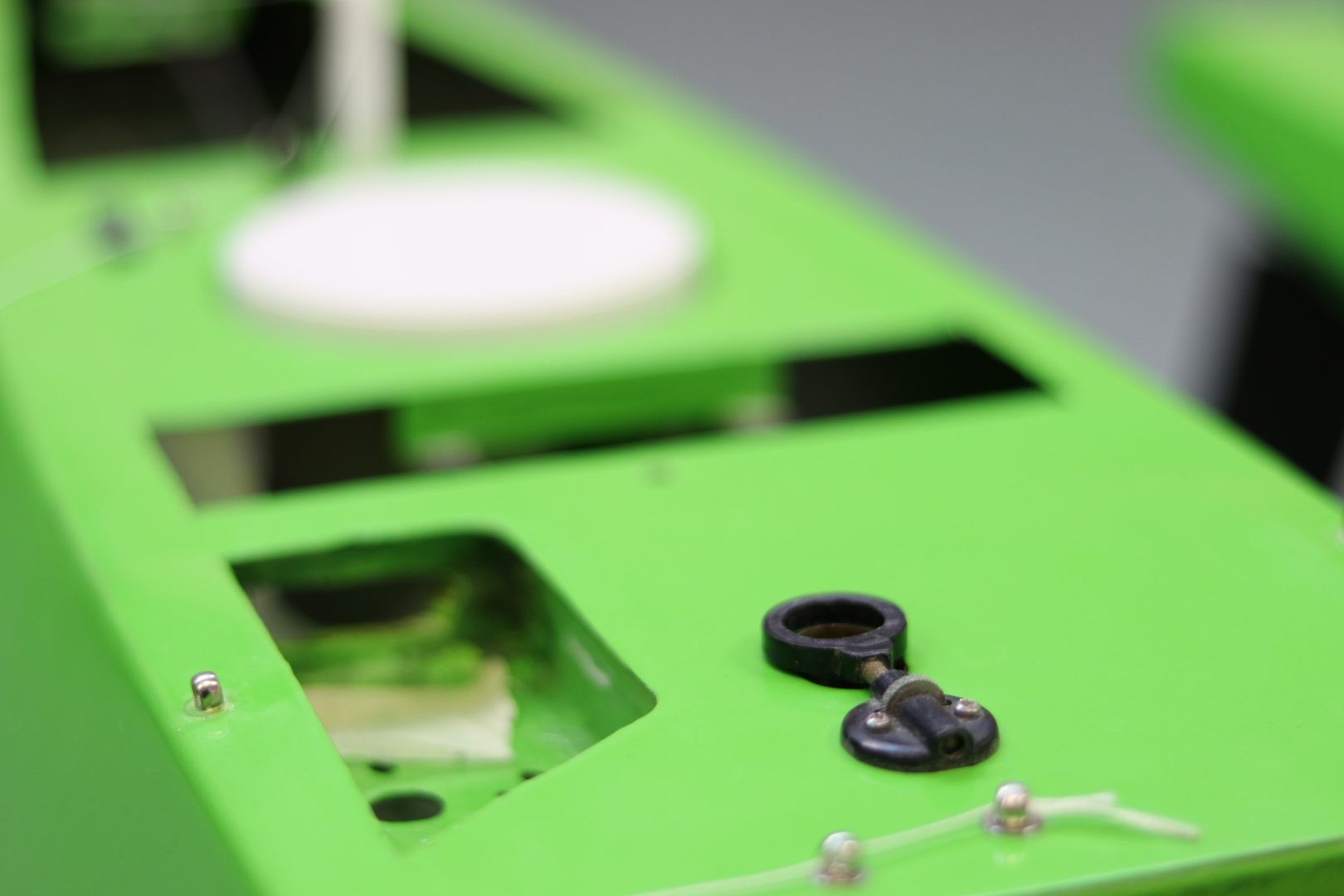
The Autonomous Sailboat
My Ph.D. at Plymouth University is on the subject of Autonomous Sailboat. As is the case in most robotic Ph.D.s, experimental results are important. In that regard, a full autonomous Sailboat had to be built !
With the help of past experience in robotics and industrialisation, I wanted to make a robust, simple - to use and to build - and affordable Sail-robot. This goal comes from my view on research : It is meant to help people, by sharing the knowledge and make it accessible to as many people as possible. Why make a million dollars robot for select laboratories ? It doesn’t make sense in research. Of course, sometimes the price cannot be as cheap as you want (depending on the subject you are in, the material needed, etc…), but this is not the case for our sailboat !
I will explain all the process of building this boat, from the software architecture to the hardware architecture, the choice in materials and the whole philosphy about this boat.
All the project refers to the files available here
The Hardware
Part 1 of this 2 parts series will focus on the hardware part.
There is nothing special about what has been done for the sailboat. However a lot of work has been spent on this and maybe others might find interesting all the process (this can be applied to any robots of any sorts).
What’s in there ?
To transform a sailboat (or anything) into an autonomous robot, we need to take control of everything and add “eyes” to it. We need to be able to control everything that can possibily make it move. And we need to add sensors so that it becomes aware of its environment. Add control algorithms to it and that’s basically the definition of a robot - being able to change its environment, being aware of the environment and making decisions.
In the sailboat, that means we need to control the sail and the rudder (our actuators), and we need to add the GPS (position), the IMU (heading and velocity) and the Wind Sensor (to know the force and the direction of the wind). We can actually add any sensor we want, depending in the necessities for our controls. The hardware is built to have access to all of that, and be able to apply controls to the actuators regarding the data acquired by the sensors.
We made our own computer (open-sourced and feasable by anyone !) to control all the sensors and motors. We won’t talk about the different components of the boat but mainly on the computer, where all the work has been done.
Robustness and Ergonomics
The hardware in the sailboat was built while keeping in mind robustness and ergonomics. This might sound contradictory but actually most of the time a tough product is a good product. (a good product is not necessarily a tough product). But this doesn’t seem as easy as just saying “Let’s do a robust robot with a nice design !” and that’s it. A lot of time thinking about all the potential use of the hardware must be examined and solved. The first and obvious challenge making a hardware for a sailboat is waterproofing ! (or weatherproofing).
For waterproofing you have two methods : either you seal everything completely and definitively or you work on the mechanical side a bit more to have a removable seal. We would like to make waterproof boxes for our sensors and our boards. Now when you look at tupperwares, this doesn’t seem difficult : you just need a rubber band as a sealant and a way to close the cover by pressing the rubber against the box. In most cases, that system works and is mostly what is done in waterproofing. But you also have to consider that there are electric cables going from one box to the other. So the connectors have to be waterproof too ! And one last thing to consider is that we will be making 3D printed boxes. 3D prints aren’t waterproof. There are always pores in the plastic where some water drops can enter. So once you printed a part, don’t forget to either sand it (by sanding it, you will close most of the pores) or apply a sealant or resine over the part. One way to help waterproofing 3D prints is also making a bigger shell. A Shell is the thickness of the walls.
Accessibility
Another thing to take into consideration is the price. To be able to have something that can be used by anyone, or at least by the biggest number of people, we have to make it accessible in price. This means keep the material as low as possible, use already made and cheap components and work more to lower the price. Accessibility also refers to the components used. If we use only a british board that can only be bought in certain regions of the world, it doesn’t make sense ! So most of the components used will either be open-sourced, free or at least buyable anywhere in the world.
In all that in mind, here are the main components of the hardware :
- Raspberry Pi
Yup, that’s all. We base our board on well-known, open-source and cheap hardware. You could find cheaper hardware, but we are sure that those components are available all around the world and that most researchers already have them. We could have actually taken only the Raspberry Pi (or only the Arduino), but some controls can be complex and we need all the calculation resource available to build those controls. That means the Arduino will do all the acquisition for the sensors and actuators, and the Raspberry Pi will focus only on the control part, nothing else.
Now, the boards are not just connected to the sailboat like that. I built an interface board, that attaches to the Arduino and the Raspberry Pi, to keep everything compact, manage the power from the battery and put robust connectors. This might be the part that is the least accessible. Since we made a custom board. But everything is of course open-source, and anyone could ask a third-party to make them, such as we did. For example from SeeedStudio : 4.90$ for 10 boards (price at moment of writing).
The board was made with KiCad an Open-Source EDA (PCB CAD) which I highly suggest if you want to build your custom boards !
Custom board
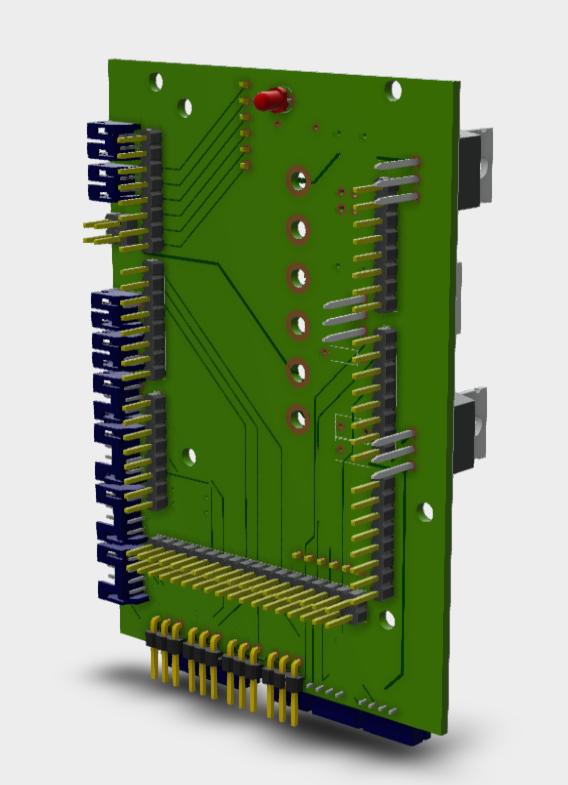
This custom board in question, as I said, is to manage the power comming from the battery and dispatch it to all the sensors and the main computers (Arduino and Raspberry Pi). It’s also installed with industrial connectors - JSTs - for robustness and is compact so that it can be mounted in any boats, even small ones.
Therefore, it is not that complex of a board : 3 regulators for the raspberry pi, the motors and the Arduino, and the sensors. These regulators converts the battery input (any voltage from 5V to 24V) to 5V constant for all the components. Most of the pins from the Arduino are linked to JST connectors to connect the sensors to the board securely, instead of connecting them on the socket header of the arduino (which is really not robust). And that’s about it.
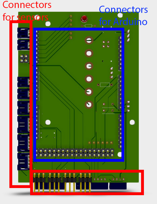
The board connects to boath the Arduino and another custom board which connects to the Raspberry Pi. They stack altogether in a 70mm x 130mm x 50mm Volume.
Connections
This stack of board that makes our main computer for our autonomous boats is then connected to all the sensors and motors of the boat to make it fully autonomous. Check the next post to see what software goes inside this hardware.
Welcome to Fenix Autopilot!
Make an autopilot by your own!
Fenix Autopilot is a DIY project aimed to provide an alternative to commercial autopilots.
The definitive Opensource autopilot for small to medium sailing boats!
I am a passionate of sail cruising. In my aim to equipe my weekender boat, I faced the need for navigation aids. Disregarding the reduction of costs that electronics have suffered, a basic navigation system is still very expensive and out of my budget.
I may understand there are many other people also interested in such a system but not able to find a complete and documented solution to be adopted.
3 Working modes: Stand-by, Auto and Waypoint Tracking
Android App connected with Bluetooth
OpenCPN Integration
Electronic compass and linear actuator calibration from Android App
NMEA Interface
Out of course alarm
Plug and play: Minimum installation and configuration required
Open I/F: develop your own autopilot controller
Automatic deadband
Sailboat autopilot
This is my construction of an autopilot that, in the end, is supposed to steer a sailboat to a certain wind angle. This history starts a few years ago, and has only been actually tried out on the boat the last two summers. I started and old thread on this forum regarding the use of PID in autopilot construction. That discussion is over and this is the new thread about the pilot itself.
The goal is to have the autopilot following a wind angle. That is, correcting the heading depending on changes in wind direction.
Today is steers the boat really nice on compass course. Now I'm working on the function to take wind angle into account.
Hardware Tilt compensated compass - LSM303DLH Arduino Nano on Custom PCB Wind Vane - based on hall sensor AS5030 Linear actuator - Concentric LACT6-12V-20 Motor position controller - Pololu jrk 21v3
Interesting thread. Looking through your first thread, what became the result? Could you use the sketch as it was first designed?
Hmm...I don't know which of the "first designs" you are referring to actually. Its based on the PID-library, which it was from the beginning as well. The D-gain in the PID-function makes the rudder centralize.
Sorry for not being precise enough, I am referring to the sketch in your first thread. I have tried to achieve the same thing - to get a servo acting as a rudder based upon the PID-library with a potentiometer as an input variable. I ran into the same problem as you did, the servo would not return to its centre position. However, setting only the P-value to 1 or 2 and the I- and D value to 0 made the servo react nicely. When the pot was set to the same value as the Setpoint, the rudder went back to its centre position as it is supposed to.
May I ask what became your final PID settings.
Sounds good! Right now I'm in the ballpark of P=2.00, I=0.20, D=0.20. But this needs to be dynamically adjusted according to the situation.
Are you working with a scale model boat or a full size ship?
Tobbera: Sounds good! Right now I'm in the ballpark of P=2.00, I=0.20, D=0.20. But this needs to be dynamically adjusted according to the situation. Are you working with a scale model boat or a full size ship?
Very close to my own conclusion - the PID values needs to be set in the environment where the PID is doing its work. I'm on a full scale project. The PID is supposed to control a reversible hydraulic pump through a Pololu Qik 2s12v10 Dual Serial Motor Controller. The servo that I'm using right now is only to validate the output from the test code, and it seems to be working quite well with the proper PID settings.
May I ask about the progress in your own project and your experience using the actuator?
My solution works very well. It has steered the boat for several hours. I have even tried to input wind data which works surprisingly well at this early stage.
The electric actuator might be a bit slow in the heavy conditions, but I think I can mount it closer to the rudders rotational center, because its really strong. That way I will gain speed and range of movement.
If a smaller motor controller is sufficient for your hydraulic drive, I have made a custom PCB that accepts Teensy 3.1 and Pololu jrk 21v3 motor controller , plug and play. Can post a picture of it later.
Tobbera: ... Can post a picture of it later.
Please do...
Nowadays its based on Teensy 3.1 for more processing power. My float/double averaging of compass and wind data bottomed out my old Arduino Nano. Now there is a lot more headroom. To this I have added a hefty enclosure and some good buttons.

And here is a video ass well! (Of the old Nano version)

The link seems to be broken. At your convenience - please provide correct url.
Now its OK!
I am in a similar project. My RabadakPilot is an autopilot Arduino based also. Please see my Youtube channel to know all my steps on project. Just make a search on Youtube with "rabadakpilot". I'm very open to share ideas. Please fell free to contact me.
Warm Regards from Portugal
Rabadak Pilot
Checking back in here - did you guys end up with roughly the same PID starting values? I've got a scale autonomous sailboat (3'), and am having a hard time tuning the PID. I've been starting with a much larger D value (P,I,D of 1, 0.001, 5), but will give the ones quoted above a try next time I take it out.
Just for anyone who looks here. I also built an autopilot on a Nano for our 37 foot sailboat. We sail (or motor) about once a week on the autopilot for over a year now.
I have been in all conditions with it, flat calm to waves of 3-4 metres and winds up to 45 knots. Right now it is just a simple PID hooked to a cheap compass board. For the steering I had a steering pump already on the boat from an old Wagner autopilot, so I adapted it to work with that.
I do plan to improve the algorithm some, but I have found that a simple PID also works.
Just for anyone who wonders if it will work. This summer we sailed around Vancouver Island using it That would be approx 700nm which includes the Pacific Ocean as well as thousands of miles around the Strait of Georgia.
I have posted the code I am using here. It is not organized very well, but just in case it helps anyone. GitHub - scottburch/autopilot: Arduino based autopilot
Hi there and thanks for post. Do you have an hardware layout overview to share with us other than the image Diagram1.png.
Related Topics
- Blog Home >
Cascading LED stair lights prevent late night tumbles — and put on a show during parties
Hacking a USB battery bank to gather telemetry
Opa is an open source boat bot that navigates the open water
Starting with an idea in 2019, Redditor wesgood has been steadily working on the Opa — an autonomous 3D-printed boat that can navigate open water while relaying its telemetry back in real-time to a client device over WiFi. After creating a small prototype, Wes built a second one that featured a pair of pontoons held together with a couple of struts and a central platform. This design contains a single water jet that is situated in the back of each pontoon that takes in water and shoots it out at a high velocity, similar to a jet ski. Best of all, they can be independently throttled which eliminates the need for a rudder.
As far as circuitry goes, the Opa houses an Arduino Mega that has a custom shield on the top for controlling the pump motors and reading data from the onboard 9-DOF IMU and battery voltage/current sensors. An auxiliary Raspberry Pi runs Ubuntu Server, and its job is to coordinate data coming from a GPS receiver and information from the Arduino Mega with a wireless client device.
After getting the necessary software loaded onto the Arduino and Raspberry Pi, Wes placed them inside of a watertight enclosure on the top of the boat. His mobile app could then be used to see relevant telemetry, power consumption, and the current location of the raft overlaid on a map. Additionally, the user has the option to manually pilot the boat if they so desire as well.
To see more information about how the Opa was developed, visit Wes’ Imgur gallery here .
Please ensure that JavaScript is enabled in your browser to view this page.
This Arduino-Powered Boat Boasts Full Autonomy, Plus LoRa and GSM Cellular Remote Control
Built over a year and a half, this boat uses three arduinos, up to two lead-acid batteries with solar charging, and packs 3d-printed parts..
Pseudonymous maker "TicsDaily" has shown off an Arduino-driven boat, offering a full autopilot mode as well as manual control over LoRa and cellular GSM radios from a 3D-printed touchscreen controller.
"I've been working on it for a year and a half," TicsDaily explains of the project. "It has three separate microprocessors that all talk to each other in the boat and then a separate one that it communicates with over RF. Nothing that it uses was built in, everything is separate parts built and programmed from scratch."
The boat uses what its creator describes as a "terribly-designed military style hull — you could hit this with a sledgehammer and it would not break," a 3D-printed steering mechanism connected to a servo, a solar panel, up to two sealed lead-acid batteries, and three internal microcontrollers each with a given duty.
"I [...] wrote quite a decent autopilot GPS waypoint based navigation system, it uses the GPS and also the electronic tilt compensated compass I designed," TicsDaily explains. "The control box also let you skip or set new waypoints as long as both the boat and the control box have mobile phone signals. The boat has two large rechargeable batteries in it it and it reports its location to the receiver box."
"I have written a manual control program over LoRa and GSM, but its primary mode is self navigating with no need for the LoRa or GSM connection. The areas I will likely use it will have cellphone signals. You can get a phone signal all round the coast of the UK and even right into the middle of the English channel."
More details are available on TicsDaily's Reddit thread . So far, no design files or schematics have been publicly released.
Latest articles
Sponsored articles, related articles.
Navigation Menu
Search code, repositories, users, issues, pull requests..., provide feedback.
We read every piece of feedback, and take your input very seriously.
Saved searches
Use saved searches to filter your results more quickly.
To see all available qualifiers, see our documentation .
- Notifications
Arduino autopilot for small boats
igabric/Arduino_boat_autopilot
Folders and files, repository files navigation, arduino autopilot for small boats - short description.
This project was created with the goal of creating a low-cost device for automatic navigation using the arduino mega microcontroller interface. The picture shows the finished device with all parts installed in the control box. 4 buttons installed on the control box, 1 rotary encoder and a remote control with 4 buttons are used to set and control the device. Steering is provided by the use of a stepper motor and a threaded rod, which enables the steering wheel to be turned by approximately 5 degrees in each direction.

The power supply of the microcontroller and the stepper motor driver are separate. The main power source is the ship's batteries, which are charged using photovoltaic panels. The voltage on the accumulators is between 13 and 14 V which is fine for the stepper motor driver, but too high for the arduino microcontroller. Therefore, powermodule DC-DC 15-80 to 12V step-down power supply converter is used to power the microcontroller. Since the stepper motor driver is built into the control box, the heatsink part faces outwards to promote heat dissipation and reduce the heating of the microcontroller. The temperature in the control box is continuously controlled using a thermistor. In the event that the temperature exceeds a critical value (which can be adjusted in the device settings), an alarm is triggered and the operation of the stepper motor is disabled.The parts installed in the control box are shown in the picture:

Settings and device management are achieved through the menu system shown in the images below.
Init menu layout.
Used for the initial positioning of the steering wheel and to setting the system.
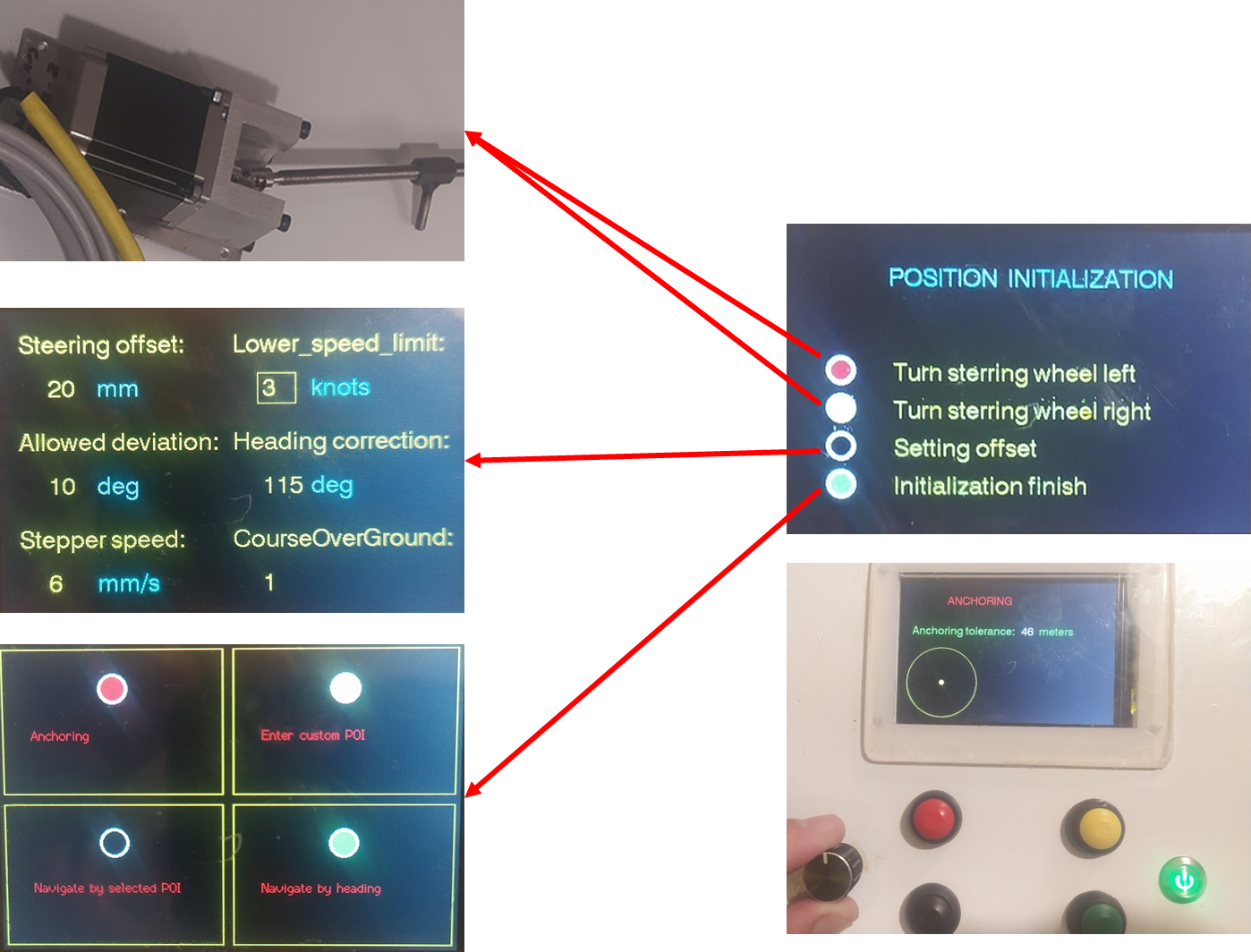
Main manu layout
Used for the function of anchoring, manual control and automatic control of the boat.

Programming Arduino
Program flow diagrams.
The simplified flow charts shown below are only a general indication of how the program works. The program modules contains a lot of details that significantly affect the functionality of the device.
** Main program flow diagram: **
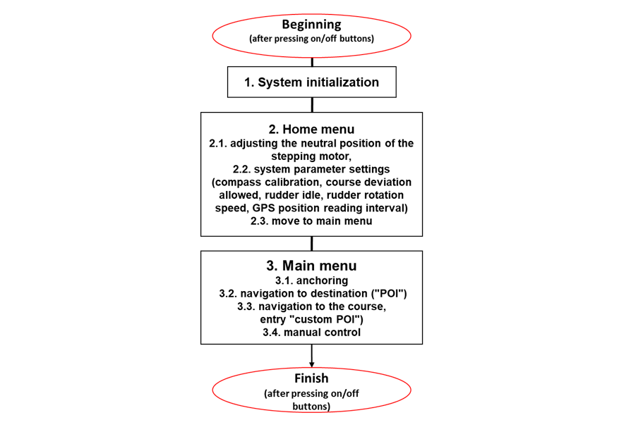

** Initialization flow diagram: **

** Flow diagram for "manually" setting the neutral position of the rudder: **
Since the use of encoders is not provided for determining the initial position of the rudder, it is necessary to "manually" adjust the neutral position of the rudder before starting the automatic operation of the autopilot.
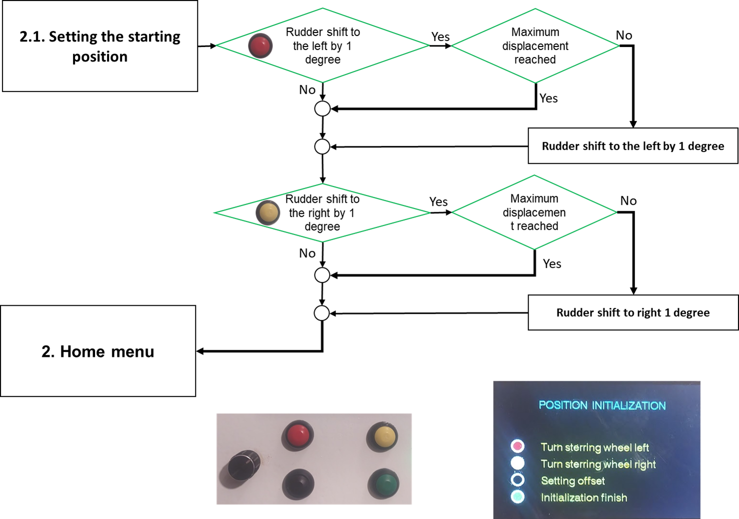
** Flow diagram for system parameter settings: **
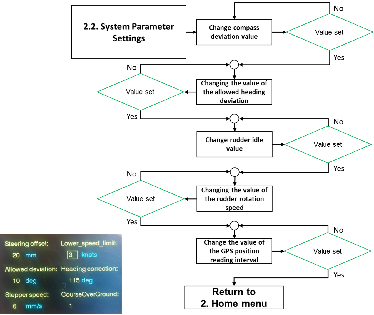
** Flow diagram for autopilot main menu: **
The main menu consists of six possible choices, two of which are hidden. The most important functionalities are navigation according to the given course and navigation according to the given destination. Applying navigation to a set course does not take into account drift due to wind and sea currents, making the final destination unreliable. In this case, the autopilot tries to maintain the given course. By applying navigation to the destination (set longitude and latitude of the destination), the course is corrected during navigation, i.e. calculated based on the current position and the position of the destination. This method of navigation is reliable, and the error depends on the precision of the GPS device (for cheaper devices, it is of the order of 10 m). The next functionality is the anchoring function. By calling this function at the moment of lowering the anchor, the current GPS position is recorded and the permitted deviation from the current position can be entered. If during the stay on the anchor there is a greater deviation than allowed (the anchor has loosened), an alarm (buzzer) is activated. By starting the microcontroller, multiple points of interest (POIs) stored on the SD card are loaded. The program enables the entry of one custom POI that can be used within the navigation function to the destination (fourth function in the main menu). The fifth hidden function refers to the manual control of the boat, which is achieved by pressing the button of the rotary encoder. Calling this function enables control using the buttons on the control box or using the remote control. The sixth function refers to the return to the home menu.
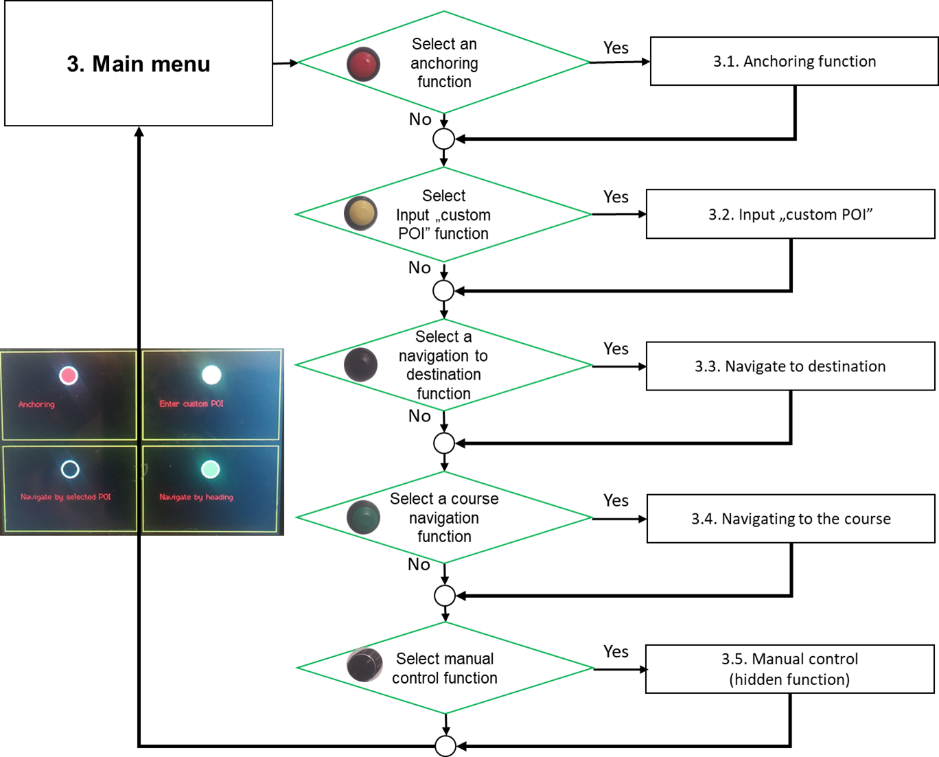
** Flow diagram for anchoring function: **

** Flow diagram for input custom POI coordinates: **
Custom POI can be entered by entering two digits at a time to speed up coordinate entry. Coordinates are entered in decimal notation. Each entry must be confirmed by pressing the button on the rotary encoder. The program provides for the input of coordinates with 6 decimal places, although the flow diagram shows the input of only 4 decimal places.
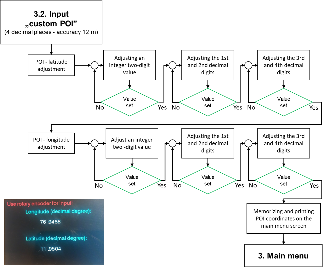
** Flow diagram for navigation to destination (point of interest): **
Navigation towards the desired destination is done by first choosing a destination from the available database stored on the SD card or a custom POI that has been previously defined. After selecting the destination, the current location is read and the course towards the destination is calculated. If the speed of the boat is higher than the minimum required, which is defined in the program settings, it is checked whether the deviation of the current course from the budget is greater than the allowed tolerance. If the course deviation is greater, the rudder is turned in the appropriate direction. The process is repeated after 5 seconds. If the deviation of the course from the budget is less than allowed, the rudder returns to the neutral position. In the loop there is also the possibility to return to the main menu. In this way, the maximum precision of the navigation path is ensured, regardless of the wind and sea currents, because the course is recalculated every 5 seconds ("course over ground").
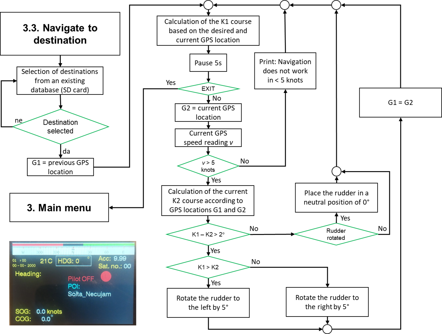
** Flow diagram for navigation to desired course: **
Navigation towards the desired direction (course) starts with entering the numerical value of the desired course. After that, the current GPS position (previous position) is read. Then there is a pause of 5 seconds after which the new current GPS position (next position) is loaded. Based on the two read positions, the current exchange rate is calculated. If the speed of the boat is higher than the minimum required (defined in the system settings), the current and desired course are compared. If the deviation is greater, the rudder is turned in the appropriate direction. Then the next position is declared as the previous position and the loop is repeated. If the deviation is less than allowed, the rudder returns to the neutral position. In the loop, it is possible to return to the main menu.
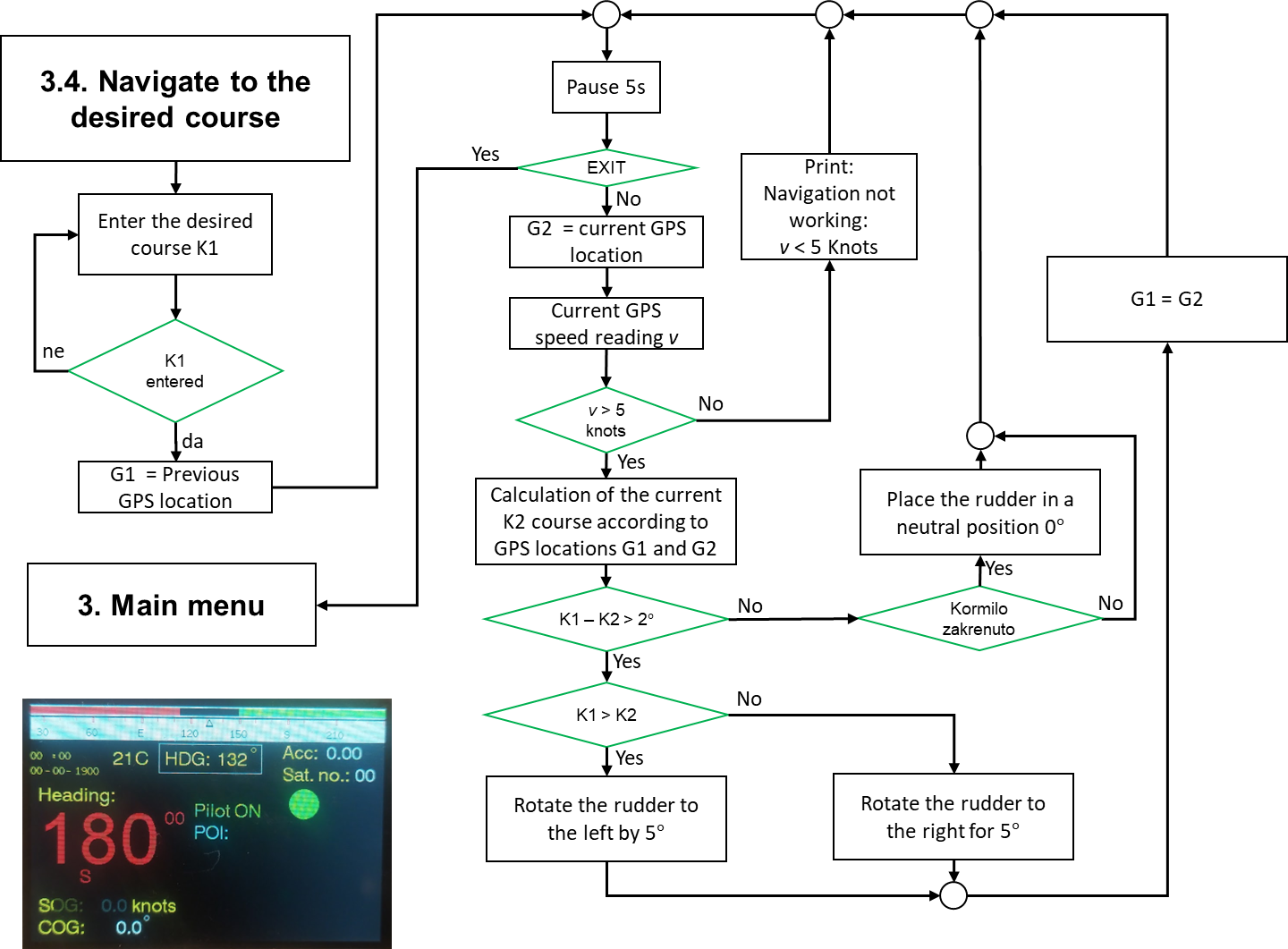
** Flow diagram for manual control: **
Starting the menu for manual control is done by pressing the button on the rotary encoder. This makes it possible to turn the rudder using the buttons on the device housing or using the remote control. The upper two buttons are used to gradually turn the rudder to the left or right, while pressing either of the lower two buttons returns the rudder to the neutral position. In the loop, it is possible to return to the main menu.

** Used components: **
- TB6600 Single Axis 4A Stepper Motor Microstep Driver 9~40V Micro-Step - 1Pcs
- Nema 23 Stepper Motor 3Nm/1.9Nm/1.26Nm 4-lead 2.8A/4.2A - 1Pcs
- Beitian BN-800 Dual Module with Antenna Compass HMC5883L - 1Pcs
- Mini 12mm Waterproof Momentary ON/OFF Push Button Round Switch - 4Pcs
- 12mm Metal Push Button Switch Waterproof LED Light Momentary Latching - 1Pcs
- 24V / 12V to 5V 5A powermodule DC-DC step-down power supply converter - 1Pcs
- 315MHz/433MHz 4Buttons RF Remote Control - 1Pcs
- 4 Channel 433MHz RF Wireless Remote Control Learning Decoding Receiver Module - 1Pcs
- 3.2 Inch MEGA2560 Display Module HX8357B 480x320 TFT LCD Screen - 1Pcs
- 40 pcs Dupont Cables M-F Jumper Breadboard Wire GPIO Ribbon for connecting TFT LCD with Arduino MEGA - 1Pcs
- MEGA 2560 R3 Arduino komp. Mikrokontroller Board Atmel ATmega2560 - 1Pcs
- Several Dupont Cables M-F, M-M, F-F Jumper Breadboard Wire for wiring
- NTC 3950 Thermistor 100KOhm - 1Pcs
- Resistor 100kOhm - 1Pcs
- KY-040 Rotary Encoder Module - 1Pcs
** Wiring diagram: **

Continue to site >>>

About | Contact | Advertise
- Microcontroller Based Projects
Build a Simple Arduino RC Boat that can be Controlled Wirelessly using 433 MHz RF Modules
In this project, we will build a remote-controlled Arduino Air-Boat that can be controlled wirelessly using the 433 MHz RF Radio Modules . We will control this boat using a homemade remote control by building our own 433 MHz transmitter and a receiver module. In the case of remote-controlled devices or communication between two devices, we have a lot of options like IR, Bluetooth, internet, RF, etc. When compared to IR communication, radio communications have some advantages like more range and it doesn’t require a line of sight connection between the transmitter and receiver. Also, these modules can do two ways of communication, meaning it can transmit and receive at the same time. So using this 433MHz RF module, let’s build an Arduino RC Boat in this tutorial.
We have previously built many remote-controlled projects using these 433Mhz RF modules for either controlling a Robot like this RF controlled Robot or for Home Automation applications to Control Home appliances using RF . Apart from using RF modules, we have also built a Bluetooth Controlled Raspberry Pi Car and a DTMF Mobile phone controlled Arduino Robot previously. You can also check out these projects if you are interested.
Components Required for Arduino RC Boat

- 433MHz transmitter and receiver
- Arduino (any Arduino, to reduce the size I am using promini)
- HT12E and HT12D
- Push buttons- 4Nos
- Resistors- 1mega ohm, 47k ohm
- L293d Motor Driver
- 9V Battery (I am using a 7.4-volt battery)- 2Nos
- 7805 regulator- 2Nos
- DC motors- 2Nos
- Motor leaf or propellors(I am using homemade propellors)- 2Nos
- .1uf capacitor- 2Nos
433MHz RF Transmitter and Receiver Modules

These types of RF modules are very popular among makers. Because of their low cost and simplicity in connections. These modules are best for all forms of short-range communication projects. These modules are ASK (Amplitude Shift Keying) type RF modules, Amplitude-shift keying (ASK) is a form of amplitude modulation that represents digital data as variations in the amplitude of a carrier wave. In an ASK system, the binary symbol 1 is represented by transmitting a fixed-amplitude carrier wave and fixed frequency for a bit duration of T seconds. If the signal value is 1, then the carrier signal will be transmitted; otherwise, a signal value of 0 will be transmitted. That means they usually draw no power when transmitting Logic “zero”. This low power consumption makes them very useful in battery-operated projects.
433MHZ RF Transmitter

This type of module is super tiny and comes with 3 pins VCC, ground, and data. Some other modules come with an extra antenna pin. The working voltage of the transmitter module is 3V-12V and this module doesn't have any adjustable components. One of the major advantages of this module is the low current consumption, it requires almost zero current to send bit zero.
Block Diagram of Arduino RC Boat Transmitter

In the above block diagram, there are four pushbuttons (Control Buttons), these pushbuttons are for controlling the direction of the boat. We have four of them for forward, backward, left, and right. From the pushbuttons, we get logic for controlling the boat but can’t directly connect to the encoder that's why we used the Arduino. You might think why I used Arduino here, it is simply because we need to pull down two parallel data inputs of the encoder at the same time for a backward and forward movement that can’t be achieved with just pushbuttons. Then the encoder encodes the coming parallel data to serial outputs. Then we can transmit that serial data with the help of an RF transmitter.
Circuit Diagram of the Arduino RC Remote (Transmitter)
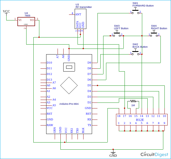
In the above circuit, you can see one side of all four pushbuttons connected to four digital pins of Arduino (D6-D9) and all the four other sides connected to the ground. That is when we press the button, the corresponding digital pins get a logic low. The four parallel inputs of the HT12E encoder connected to another four digital pins of Arduino (D2-D5). So with the help of Arduino, we can decide the input of the encoder.
And talking about encoder HT12E is a 12-bit encoder and a parallel input-serial output encoder . Out of 12 bits, 8-bits are address bits that can be utilized for controlling multiple receivers. The pins A0-A7 are the address input pins. In this project, we are controlling only one receiver, so we don't want to change its address, so I connected all address pins to the ground. If you want to control different receivers with one transmitter, you can use dip switches here. AD8-AD11 are the control bit inputs. These inputs will control the D0-D3 outputs of the HT12D decoder. We need to connect an oscillator for the communication and the oscillator frequency should be 3KHz for 5V operation. Then the resistor value will be 1.1MΩ for 5V. Then I connected the output of the HT12E to the transmitter module. We already mentioned, the Arduino and rf transmitter module, both of these devices work on 5V high voltage will kill it, so to avoid this, I added the 7805, voltage regulator. Now we can connect (Vcc) 6-12volt any type batteries to input.

Building the RC BOAT Transmitter Circuit
I soldered every component on a common PCB. Remember we are working on an RF project so there are a lot of chances for different types of interferences so connect all components very closely as much possible. It's better to use female pin headers for Arduino and the transmitter module. Also, try to solder everything on the copper pads instead of using extra wires. Finally, connect a small wire to the transmitter module that will help to increase the total range. Before connecting the Arduino and transmitter module, double-check the voltage of the lm7805 output.

The above image shows the top view of the completed RC Boat transmitter circuit and the Bottom view of the completed RC Boat Transmitter circuit is shown below.

Building the Arduino RC Boat Transmitter Enclosure
A decent body is necessary for the remote. This step is all about your ideas, you can create a remote body with your ideas. I am explaining how I made this. For making a remote body, I choose 4mm MDF sheets, you can also choose plywood, foam sheet, or cardboard, then I cut two pieces from that with a length of 10cm and breadth of 5cm. Then I marked the positions for the buttons. I placed the direction buttons on the left side and forward, backward buttons on right. On the other side of the sheet, I connected the push buttons to the main transmitting circuit. Remember a normal pushbutton has 4 pins that are two pins for each side. Connect one pin to Arduino and the other pin to the ground. If you are confused with that, please check it with a multimeter or check the datasheet.

After connecting all these things, I placed the control circuit in between the two MDF boards and tighten with some long bolt (please refer to the below images if you want). Once again creating a good body is all about your ideas.

433Mhz Receiver Module

This receiver also very tiny and comes with 4 pins VCC, ground, and the two middle pins are data out. The working voltage of this module is 5v. Like the transmitter module, this is also a low power module. Some modules come with an extra antenna pin but in my case, that is not present.
Block Diagram of the Arduino RC Boat Receiver

The above block diagram describes the working of the RF receiver circuit. First, we can receive the transmitted signals using the RF receiver module. The output of this receiver is serial data. But we can't control anything with this serial data that's why we connected the output to the decoder. The decoder decodes the serial data to our original parallel data. In this section, we don't require any microcontrollers, we can directly connect the outputs to the motor driver.
Circuit Diagram of Arduino RC Boat Receiver
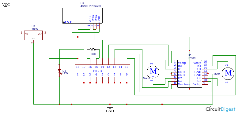
The HT12D is a 12-bit decoder which is a serial input-parallel output decoder . The input pin of the HT12D will be connected to a receiver that has a serial output. Among the 12-bits, 8 bits (A0-A7) are address bits and the HT12D will decode the input if only it matches its current address. D8-D11 are the output bits. To match this circuit to the transmitter circuit, I connected all the address pins to the ground. Data out of the module is the serial type and the decoder decodes this serial data to original parallel data and we get out through D8-D11. To match the oscillation frequency should connect the 33-56k resistor to oscillator pins. Led on the 17th pin indicates the valid transmission, it only lit after when the receiver connected to a transmitter. The voltage input of the receiver is also 6-12 volts.

To control motors, I used the L293D IC, I choose this IC because to decrease the size and weight and this IC is best for controlling two motors in two directions. L293D has 16 pins, the below diagram shows the pinouts.

1, 9 pins are the enable pin, we connect that to 5 v to enable motors 1A, 2A, 3A, and 4A are the control pins. The motor will turn to the right if the pin 1A goes low and 2A goes high, and the motor will turn to the left if 1A goes low and 2A high. So we connected these pins to the output ps of the decoder. 1Y, 2Y, 3Y, and 4Y are the motor connection pins. Vcc2 is the motor driving voltage pin, if you are using a high voltage motor, then you connect this pin to the corresponding voltage source.
Building the Receiver Circuit of Arduino RC Boat
Before building the receiver circuit, you should remember some important things. The important one is the size and weight because after building the circuit, we need to fix it on the boat. So if the weight increases, that will affect the buoyancy and movement.
So same as in the transmitter circuit, solder every component in a small common PCB and try to use minimum wires. I connected pin 8 of the motor driver to 5v because I am using 5V motors.

Building the RC-BOAT

I tried different materials to build the boat body. And I got a better result with thermocol sheet. So I decided to build the body with thermocol. First, I took a 3cm thick thermocol piece and place the receiver circuit on top, then I marked the shape of the boat in thermocol and cut. So this is my way to build the boat, you can build according to your ideas.
Motors and Propellers for Arduino Air Boat
Once again weight matters. So choosing the correct motor is important, I choose 5volt, n20 type normal dc motors which is small and weightless. To avoid the RF interferences should connect 0.1uf capacitor parallel to motor inputs.

In the case of propellers, I made propellers using plastic sheets. You can buy propellers from the store or you can build your own both will work just fine. To build the propellers, first, I took a small plastic sheet and cut two small pieces from it and I bend the pieces with the help of candle heat. Finally, I put a small hole in its center for the motor and fixed to the motor that's it.

Working of Arduino RC Boat
This boat has two motors lets call it left and right. If the motor moves to clockwise also (the position of the propellor also depends) propellor sucks air from the front and exhaust to the backside. That generates forward drag.
Forward movement : If both the left and right motors rotate to clockwise that will forward movement
Backward movement : If both the left and right motors to rotate counterclockwise(that is propeller sucks air from the backside and exhaust to the front side )that will make backward movement
Left movement: If only the right motor rotates that is boat get only drag from the right side that will the boat to move to the left side
Right movement : If only the left motor rotates that is boat gets only drag from the left side that will make the boat move to the right side.
We connected the motors driver's input to four output bits of the decoder(D8-D11). we can control these 4 outputs by connecting the AD8-AD11 to the ground that is the buttons in the remote. For example, if we connect AD8 to the ground that will activate the D8. So such a way we can control the two motors in two directions using these 4 outputs. But we can't control two motors by just one button (we need that for forward and backward movement) that's why we used the Arduino. With help of Arduino, we can select the input data pins as our wish.
Arduino Programming of the RC Boat
The programming of this boat is very simple because we want only some logic switching. And we can achieve everything with basic Arduino functions. The complete program for this project can be found at the bottom of this page. The explanation of your program is as follows
We start the program by defining the integers for four input buttons and decoder inputs pins.
In the setup section, I defined the pin modes. That is, the buttons are connected to digital pins so these pins should define as input and we need to get output for the input of the decoder so we should define those pins as output.
Next in the main loop function, we will read the button status using the digitalread function of Arduino. If the pin status goes low that means the corresponding pin is pressed then we will execute the conditions as like follows-
That means the forward button is pressed
This will pulldown m1 and m2 of the encoder this will activate both motors on the receiver side. Similarly, for backward movement
For left movement
For right movement
After compiling the code, upload it to your Arduino board.
Troubleshooting : Place the boat on the water surface and check whether it is moving correctly if not try to change the polarity of motors and propellers. Also, try to balance weight.

The complete working of the project can be found in the video linked at the bottom of this page. If you have any questions leave them in the comment section.
Ask Our Community Members

- Log in or register to post comments

Join 100K+ Subscribers
Your email is safe with us, we don’t spam.
Be a part of our ever growing community.
Copyright © 2023 Circuit Digest . All rights reserved.
Arduino RC Boat

Introduction: Arduino RC Boat

I found my old wooden boat and decide make it RC controlled. So I make ribs from balsa and glued them to make voluminous body allowed heavy load like battery, arduino, motor and more.
Step 1: Planking

I used many narrow balsa strips to planking. Using pins I hold them on their place until the glue has hardened.
Step 2: Grinding

After glued all strips come on grinding. Hours and hours grinding to make smooth body.Then I varnish 3-5 times to make it waterproof
Step 3: Making Keel

I glued some balsa offcuts and then I cut them to requested shape with sharp knife.
Step 4: Counterpoise

I found that the ship is unable to sail, so i must cut away the keel to fill body with some piece of fishing lead, to set centroid down.
Step 5: ...

But after I glued it back, I tried the boat on water and it still floated bevel. So I must cut off keel again and use more lead. (I used 0,5kg of lead)
Step 6: Painting
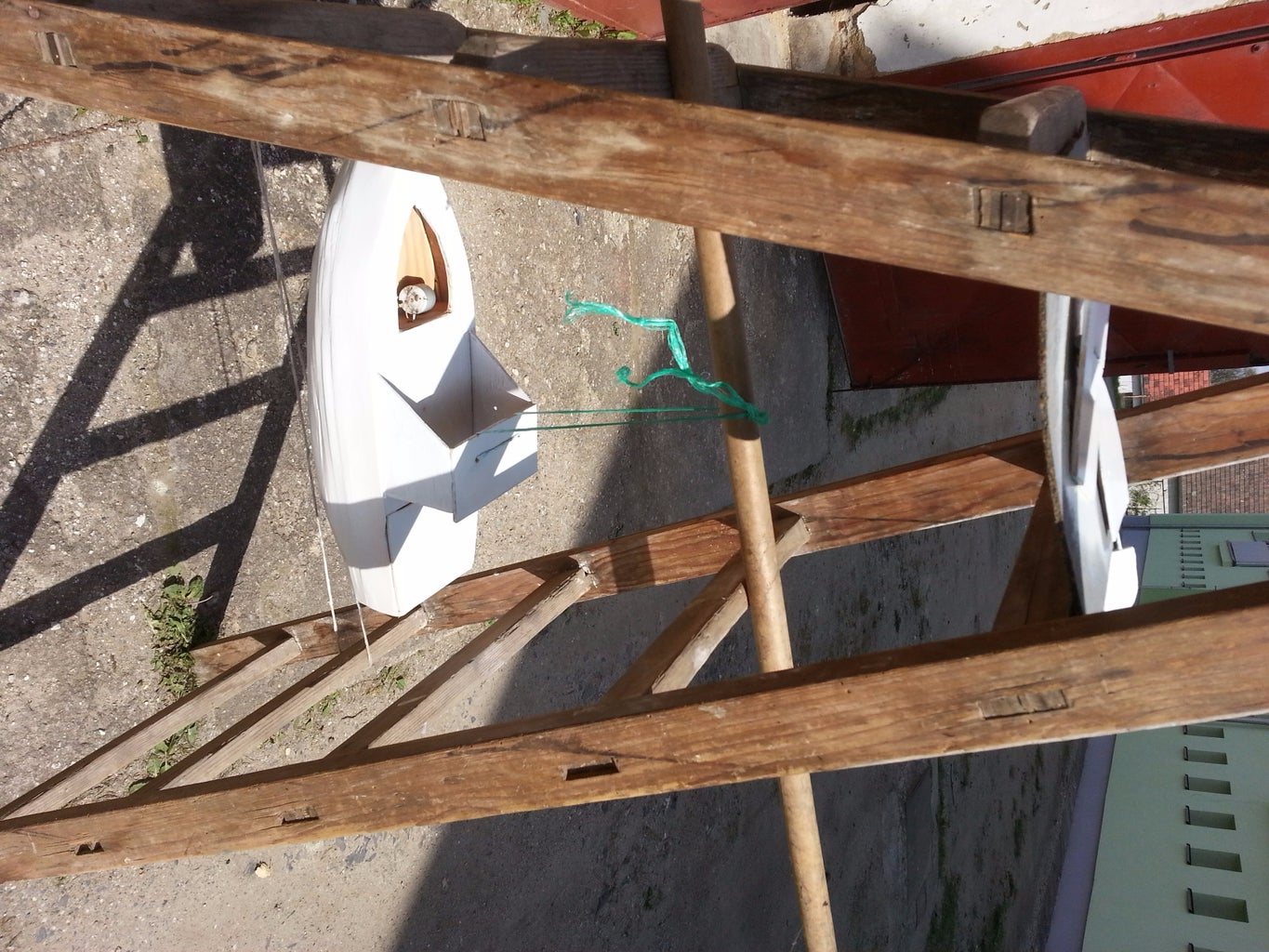
For paint i used paint in spray.
Step 7: Controller - Wiring and Function

This is my controller to control my boat. It can be more simpliest to control boat but my plan is controlling plane in the future.
- Arduino nano
- Srews and nuts
- Perspex or another material
- Battery connector
- Capacitor 10 uC
About nrf24l01:
Info about nrf24l01: https://arduino-info.wikispaces.com/Nrf24L01-2.4GH...
Library RF24: https://tmrh20.github.io/RF24/
Demo code: http://forum.arduino.cc/index.php?topic=381973.msg..
Program function:
- vertical is forward and backward motor
- horizontal - nothing
- vertical - nothing
- horizontal is left and right steering
- buttons are connected to one analog pin. Every buttons has different resistor value, so arduino identify, which button is pushed. It can be programed to anything in receiver side
- These leds tunr on whned button or switch under the led is on.
- Led is lighting when controller is succes connected to boat
Led is fadeing, it signaling that controller is tured on, it'll turn off when green led will turn on
Attachments
Step 8: boat wiring materials.

- 4x transistor (or H-bridge L298N)
- *tranzistor - 2x

Participated in the First Time Author Contest 2016

Participated in the Make it Move Contest 2016
Recommendations

Make it Resilient

Making Time Contest

Build-A-Tool Contest


IMAGES
VIDEO
COMMENTS
January 8, 2014. [Jack], a mechanical engineer, loom builder, and avid sailor wanted an autopilot system for his 1983 Robert Perry Nordic 40 sailboat with more modern capabilities than the one it ...
It's easy to build, based on the popular Arduino platform, and great for hobbyists who want some soldering practice! With this autopilot, an RC boat can go long distances without any human intervention, like an autonomous drone. The original idea was to mimic robotic boats like the UBC Sailbot, and the Scout (which almost successfully completed ...
All of this software is included in OpenPlotter which is like a software package for navigational aid and boat automation. The drive unit for the autopilot, bought second hand and has the capability to handle a boat of 20 tons. The arduino and the H-bridge to control the drive unit. PCBs to hold some necessary extra components. The Raspberry Pi
Autopilot2 Arduino code. arduino. 12// AUTOPILOT version 23// by Marco Zonca, 2019-20224/* 5 This sketch works as Autopilot for small sailing boats 6 Arduino Nano as CPU, Arduino Nano as watchdog, GPS BT-220 nmea, stepper motor + controller, rf315Mhz RC, 6 buttons, 7 buzzer, i2c display, 3xLEDS, i2c 24c04 eeprom, Mux 4051 for trasducers ...
Try it in the simulator: ArduRover has a basic sailboat simulator, this can be launched directly from Mission Planner. It is a great way to try out the functionality before building your own vehicle, especially if you are new to ArduPilot.
1. Arduino UNO. Project description. Code. Autopilot sketch (for Uno) arduino. 1/* 2 This sketch act as Autopilot for small sailing boats, by Marco 3 Zonca, 2019 4 Arduino UNO as CPU, Arduino Nano as watchdog, GPS BT-220 nmea, 5 stepper motor + controller, rf433Mhz RC, 6 buttons, buzzer, i2c display, 6 2 7 leds, i2c 24c04 eeprom, Mux 4051 for ...
One last watchdog is inside the Arduino. If a bug happens (no controller at all in the Sailboat), the Arduino resets and put the Return Home control. Raspberry Pi/ROS. The Raspberry Pi only does the high level control such as path-planning, intensive calculation controllers and more. The Raspberry Pi runs with ROS for its controllers.
The board connects to boath the Arduino and another custom board which connects to the Raspberry Pi. They stack altogether in a 70mm x 130mm x 50mm Volume. Connections. This stack of board that makes our main computer for our autonomous boats is then connected to all the sensors and motors of the boat to make it fully autonomous.
I have built this autopilot which steers the boat both by compass and wind angle. It's a work in progress, and more videos will be coming. Please see threat ...
Arduino Boat Autopilot - in Progress: This project was created with the goal of creating a low-cost device for automatic navigation using the arduino mega microcontroller interface. The picture shows the finished device with all parts installed in the control box. 4 buttons installed on…
Welcome to Fenix Autopilot! Make an autopilot by your own! Fenix Autopilot is a DIY project aimed to provide an alternative to commercial autopilots. The definitive Opensource autopilot for small to medium sailing boats! I am a passionate of sail cruising. In my aim to equipe my weekender boat, I faced the need for navigation aids.
Flash ArduPilot Firmware to FC (Tipp: you can use Betaflight, a common FPV drone software, for that) Install a Ground Station software like Mission Planner and connect the board (see mission planner UI in image 1) Do a basic hardware setup. calibrate gyro and compass. calibrate remote control. setup output channels.
So I've spent a bit of time over the past few months trying to rig up an arduino to a cheap RC sail boat. A major reason I've gone after a sailboat over other drones is that its power consumption isn't proportional to the distance travelled, meaning that eventually, I could strap a solar panel to it, and have it go for a substantial period of time. So - this is take one. I'm using a $100 RC ...
Tobbera July 27, 2015, 10:50am 1. This is my construction of an autopilot that, in the end, is supposed to steer a sailboat to a certain wind angle. This history starts a few years ago, and has only been actually tried out on the boat the last two summers. I started and old thread on this forum regarding the use of PID in autopilot construction.
November 16th, 2021. Starting with an idea in 2019, Redditor wesgood has been steadily working on the Opa — an autonomous 3D-printed boat that can navigate open water while relaying its telemetry back in real-time to a client device over WiFi. After creating a small prototype, Wes built a second one that featured a pair of pontoons held ...
This Arduino-powered boat can travel autonomously — and charge on the way via solar panels. (📹: TicsDaily) The boat uses what its creator describes as a "terribly-designed military style hull — you could hit this with a sledgehammer and it would not break," a 3D-printed steering mechanism connected to a servo, a solar panel, up to two sealed lead-acid batteries, and three internal ...
The Boat is made using Arduino UNO along with bluetooth module "HC-06". An android app " Arduino bluetooth controller " is used to send the commonds to ardui...
I used Arduino as a microcontroller, an ultrasonic sensor in the front, a few simple switches on the side of the boat, and a few light sensors on either side. See here for a few more photos or here for a pdf step by step. This simple little floating boat bounces off walls, can be steered with a flashlight, and won't hit something head-on.
Hello. This video includes, how to make a DIY Bluetooth control boat using Arduino. It is mainly based on the Bluetooth module known as the HC-05.OK, enjoy i...
ARDUINO AUTOPILOT FOR SMALL BOATS - short description. This project was created with the goal of creating a low-cost device for automatic navigation using the arduino mega microcontroller interface. The picture shows the finished device with all parts installed in the control box. 4 buttons installed on the control box, 1 rotary encoder and a ...
In this project, we will build a remote-controlled Arduino Air-Boat that can be controlled wirelessly using the 433 MHz RF Radio Modules. We will control this boat using a homemade remote control by building our own 433 MHz transmitter and a receiver module. In the case of remote-controlled devices or communication between two devices, we have ...
Step 8: Boat Wiring Materials. Arduino RC Boat: I found my old wooden boat and decide make it RC controlled. So I make ribs from balsa and glued them to make voluminous body allowed heavy load like battery, arduino, motor and more.
#fyp #mechanicalengineering #mechatronics #robotics #rc #boat Link for the codes : https://github.com/AbdulSamadDanish/RC-BOAT.git